
I have a 1U Datto NAS unit that I got for super cheap ($150 for 4x 3.5″ SAS3, D-1541, 4x32GB, 2400MHz, 2x 10GbaseT) that has worked quite well for me. The only downside, which is present among basically all 1U devices, is the noise.
During my research for how to control the tiny, high-RPM (like 8000+ RPM) fans, I stumbled across a thread on the FreeNAS forums – https://www.truenas.com/community/threads/script-to-control-fan-speed-in-response-to-hard-drive-temperatures.41294/. At the bottom of the post, there are a few other links to improvements. I ran the Perl logging scripts that made up the improvements a bit but I am no Perl expert so didn’t up implementing it.
I am not 100% sure of the default AsrockRack behavior but it seemed that if CPU temp >60C, both case and CPU fans would spike. My BlueIris instance sends videos over a couple times an hour, which would spike the fans, which would be annoying during my work from home weeks while I was in the basement, working.
The idea of using a PID loop to control fan speeds stuck with me though, and with the help of GitHub Copilot, I busted out a proof of concept in an hour or so during a particularly boring set of meetings. There is a very high probability this will work for Supermicro motherboards as well with only minor tweaks.
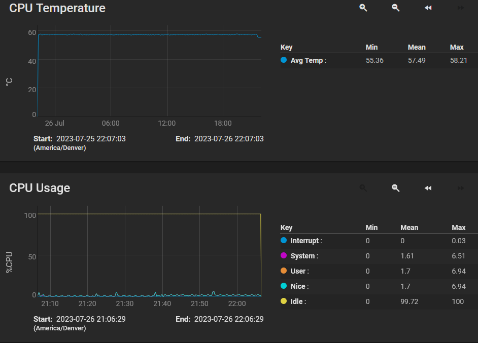
This is how well it works. Note the drop at the end is due to changing CPU setpoint from 57C to 55C. The temperature is very, very steady.
Without further ado, below is the main script (you’ll also need PID.py, which I borrowed a few years ago for the Coding a pitch/roll/altitude autopilot in X-Plane with Python series of posts). It can be run via SSH for debugging purposes (it is no fun to edit python via nano over ssh on FreeBSD), or with native commands if it detects it is running on the target system.
import logging
import time
import PID
import datetime
import socket
import subprocess

logging.basicConfig(
    format='%(asctime)s - %(name)s - %(levelname)s - %(message)s', level=logging.INFO)

# don't care about debug/info level logging from either of these packages
loggers_to_set_to_warning = ['paramiko.transport', 'invoke']
for l in loggers_to_set_to_warning:
    logging.getLogger(l).setLevel(logging.WARNING)

user = "root"
password = r"password"
host = None # this is set via hostname detection below
DESIRED_CPU_TEMP = 55.0
DESIRED_MB_TEMP = 35.0
# HDD_TEMP_THRESHOLD = 44.0 # unused
MIN_FAN_PCT = 10.0
drives_to_monitor = ['da0', 'da1', 'da2', 'da3', 'nvme0','nvme1','nvme2']

# command to set fans via ipmitool
# ipmitool raw 0x3a 0x01 0x00 0x04 0x04 0x04 0x04 0x04 0x04 0x04
					     #cpu #fan #fan #fan #fan #fan #fan ????

BASE_RAW_IPMI = 'raw 0x3a 0x01'
INITIAL_STATE = [32,32,32,32,32,32,32,32] # all 32/64 = half speed
FAN_CURRENT_STATE = INITIAL_STATE

hostname = socket.gethostname()
if 'truenas' in hostname or hostname == 'truenas-datto.home.fluffnet.net':
    host = 'localhost'
    c = None
else:
    from fabric import Connection # importing here because freebsd 13 (or whatever truenas core 13 is based on lacks pip to install packages)
    host = "10.98.1.9"
    c = Connection(host, port=22, user=user, connect_kwargs={'password': password})

current_sensor_readings = {}
cpu_temp_sensor = "CPU Temp"
cpu_fan_sensor = "CPU_FAN1"
case_fans = ["FRNT_FAN2","FRNT_FAN3","FRNT_FAN4"]
mb_temp_sensor = "MB Temp"

def limiter(input_value, min_value, max_value):
    if input_value < min_value:
        return min_value
    elif input_value > max_value:
        return max_value
    else:
        return input_value

def set_fans_via_ipmi(connection):
    # raw_ipmi_cmd = construct_raw_ipmi_cmd() # not needed unless debug and remote
    # logging.info(raw_ipmi_cmd)
    if host == 'localhost':
        result = subprocess.run(['ipmitool', 'raw', '0x3a', '0x01',
                                 '0x'+FAN_CURRENT_STATE[0],
                                 '0x'+FAN_CURRENT_STATE[1],
                                 '0x'+FAN_CURRENT_STATE[2],
                                 '0x'+FAN_CURRENT_STATE[3],
                                 '0x'+FAN_CURRENT_STATE[4],
                                 '0x'+FAN_CURRENT_STATE[5],
                                 '0x'+FAN_CURRENT_STATE[6],
                                 '0x'+FAN_CURRENT_STATE[7]], stdout=subprocess.PIPE)
    else:
        raw_ipmi_cmd = construct_raw_ipmi_cmd()
        result = connection.run('ipmitool ' + raw_ipmi_cmd, hide=True)
    #logging.info(result.stdout)

def scale_to_64ths(input_percent):
    result = input_percent / 100.0 * 64.0
    # prepend 0 to make it a hex value
    result_int = int(result)
    result_str = str(result_int)
    if len(result_str) == 1:
        result_str = '0' + result_str # turn a 0x1 into a 0x01
    return result_str

def adjust_cpu_fan_setpoint(hex_value_64ths):
    FAN_CURRENT_STATE[0] = hex_value_64ths

def adjust_case_fan_setpoint(hex_value_64ths):
    for i in range(len(FAN_CURRENT_STATE) - 1):
        FAN_CURRENT_STATE[i + 1] = hex_value_64ths

def construct_raw_ipmi_cmd():
    new_state = BASE_RAW_IPMI
    for i in range(len(FAN_CURRENT_STATE)):
        new_state = new_state + ' 0x' + str(FAN_CURRENT_STATE[i])
    return new_state

def populate_sensor_readings(sensor, value):
    current_sensor_readings[sensor] = value

def query_ipmitool(connection):
    if host == 'localhost':
        result = subprocess.run(['ipmitool', 'sensor'], stdout=subprocess.PIPE)
        result = result.stdout.decode('utf-8')
    else:
        result = connection.run('ipmitool sensor', hide=True).stdout
    for line in result.split('\n'):
        if line == '':
            break

        row_data = line.split('|')
        sensor_name = row_data[0].strip()
        sensor_value = row_data[1].strip()
        populate_sensor_readings(sensor_name, sensor_value)
        logging.debug(sensor_name + " = " + sensor_value)

def wait_until_top_of_second():
    # calculate time until next top of second
    sleep_seconds = 1 - (time.time() % 1)
    time.sleep(sleep_seconds)

def get_drive_temp(connection, drive):
    ###########################################
    # this is copilot generated, and untested #
    # not sure about row_data[0] stuff        #
    ###########################################
    if host == 'localhost':
        result = subprocess.run(['smartctl', '-A', '/dev/' + drive], stdout=subprocess.PIPE)
        result = result.stdout.decode('utf-8')
    else:
        result = connection.run('smartctl -A /dev/' + drive, hide=True).stdout
    for line in result.split('\n'):
        if line == '':
            break

        row_data = line.split()
        if len(row_data) < 10:
            continue
        if row_data[0] == '194':
            drive_temp = row_data[9]
            logging.info(drive + " = " + drive_temp)

def query_drive_temps(connection):
    for drive in drives_to_monitor:
        get_drive_temp(connection, drive)

# tune these values. the first one is the most important and basically is the multiplier for
# how much you want the fans to run in proportion to the actual-setpoint delta.
# example: if setpoint is 55 and actual is 59, the delta is 4, which is multiplied by 4 for
# 16 output, which if converted to 64ths would be 25% fan speed.
# the 2nd parameter is the integral, which is a cumulative error counter of sorts.
# the 3rd parameter is derivative, which should probably be set to 0 (if tuned correctly, it prevents over/undershoot)
cpu_pid = PID.PID(4.0, 2.5, 0.1)
cpu_pid.SetPoint = DESIRED_CPU_TEMP

mb_pid = PID.PID(2.5, 1.5, 0.1)
mb_pid.SetPoint = DESIRED_MB_TEMP

wait_until_top_of_second()

# set last_execution to now minus one minute to force first execution
last_execution = datetime.datetime.now() - datetime.timedelta(minutes=1)

while(True):
    if datetime.datetime.now().minute != last_execution.minute:
        # TODO: get drive temps
        logging.info("getting drive temps")

    query_ipmitool(c)
    cpu_temp = float(current_sensor_readings[cpu_temp_sensor])
    mb_temp = float(current_sensor_readings[mb_temp_sensor])

    cpu_pid.update(cpu_temp)
    mb_pid.update(mb_temp)

    logging.info(f'CPU: {cpu_temp:5.2f} MB: {mb_temp:5.2f} CPU PID: {cpu_pid.output:5.2f} MB PID: {mb_pid.output:5.2f}')

    # note negative multiplier!!
    cpu_fan_setpoint = scale_to_64ths(limiter(-1*cpu_pid.output,MIN_FAN_PCT,100))
    case_fan_setpoint = scale_to_64ths(limiter(-1*mb_pid.output,MIN_FAN_PCT,100))
    adjust_cpu_fan_setpoint(cpu_fan_setpoint)
    adjust_case_fan_setpoint(case_fan_setpoint)
    set_fans_via_ipmi(c)

    last_execution = datetime.datetime.now()
    wait_until_top_of_second()
As you can see, it is not quite complete. I still need to add the hard drive temp detection stuff to ramp case fans a bit if the drives get hot. Those NVMe drives sure get hot (especially the Intel P4800X I have in one of the PCIe slots – see Intel Optane P1600X & P4800X as ZFS SLOG/ZIL for details).
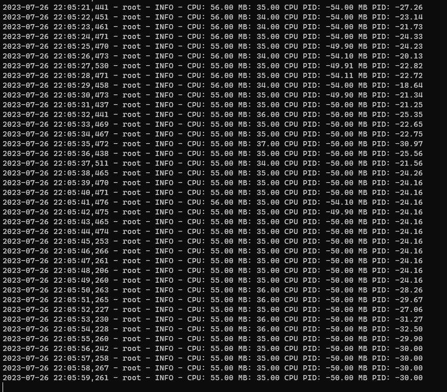
This is what the output looks like (keep in mind the -1 multiplier in the setpoint stuff!):
And here is a summary of the script provided by the ever helpful ChatGPT with some high-level summaries. I fed it the code and said “write a blog post about this”. I took out the intro paragraph but left the rest.
The Script Overview
This script leverages the PID controller – a control loop mechanism that calculates an “error” value as the difference between a measured process variable and a desired setpoint. It attempts to minimize the error by adjusting the process control inputs.
In this script, we are implementing a fan speed control system that reacts to temperature changes dynamically. Our desired setpoint is the optimal temperature we want to maintain for both the CPU (DESIRED_CPU_TEMP) and the motherboard (DESIRED_MB_TEMP).
Exploring the Script
The Python script begins by setting up the necessary libraries and logging. The logging library is used to log useful debug information, such as the current CPU temperature and fan speed, which can help you understand what’s happening in the script.
Next, we have a section where we define some constants, such as the desired temperatures and minimum fan speed percentage. It also defines a connection to the localhost or to a remote host, depending on the hostname.
It uses ipmitool – a utility for managing and configuring devices that support the Intelligent Platform Management Interface (IPMI) to control fan speeds.
The limiter() function ensures the fan speed remains within the predefined minimum and maximum thresholds. It’s important as it prevents the fan speed from reaching potentially harmful levels.
The script also includes several functions to set and adjust fan speeds, as well as to construct the appropriate ipmitool command. One thing to note is that the fan speeds are set using hexadecimal values, so there are functions to convert the desired fan speed percentages to hexadecimal.
A very useful function is query_ipmitool(). This function runs the ipmitool command, gets the current sensor readings, and stores them in the current_sensor_readings dictionary for further processing.
The script utilizes two PID controllers, cpu_pid for the CPU and mb_pid for the motherboard, with specific setpoints set to desired temperatures.
The core logic is inside the infinite loop at the end of the script. The loop constantly reads temperature sensor data and adjusts the fan speeds accordingly. The loop runs once every second, so it can respond quickly to changes in CPU and motherboard temperatures.
Conclusion
This script demonstrates a neat way of controlling fan speed in response to CPU and motherboard temperatures. It’s an effective approach to ensure that your system runs smoothly and without overheating, while minimizing noise.
Disclosure: When you click on links to various merchants in this post and make a purchase, this can result in this site earning a commission. Affiliate programs and affiliations include, but are not limited to, the eBay Partner Network.
2 replies on “Controlling AsrockRack CPU & chassis fan speeds via ipmitool & PID loops”
Thanks so much for the script, worked really well on my EPYC3251D4I-2T motherboard with TRUENAS SCALE.
I used the “Card Side Temp” as the temp monitoring for fan speed. Will post back if I have a chance to extend the NVME temp monitoring…
You are welcome! It has been working great on my machine still as well. Really silences the fans to a manageable level.