I’ve written before about building microsecond-accurate NTP servers with Raspberry Pi and GPS PPS, and more recently about revisiting the setup in 2025. Both posts focused on the hardware setup and basic configuration to achieve sub-microsecond time synchronization using GPS Pulse Per Second (PPS) signals.
But there was a problem. Despite having a stable PPS reference, my NTP server’s frequency drift was exhibiting significant variation over time. After months (years) of monitoring the system with Grafana dashboards, I noticed something interesting: the frequency oscillations seemed to correlate with CPU temperature changes. The frequency would drift as the CPU heated up during the day and cooled down at night, even though the PPS reference remained rock-solid.
Like clockwork (no pun intended), I somehow get sucked back into trying to improve my setup every 6-8 weeks. This post is the latest on that never-ending quest.
This post details how I achieved an 81% reduction in frequency variability and 77% reduction in frequency standard deviation through a combination of CPU core pinning and thermal stabilization. Welcome to Austin’s Nerdy Things, where we solve problems that 99.999% of people (and 99% of datacenters) don’t have.
The Problem: Thermal-Induced Timing Jitter
Modern CPUs, including those in Raspberry Pis, use dynamic frequency scaling to save power and manage heat. When the CPU is idle, it runs at a lower frequency (and voltage). When load increases, it scales up. This is great for power efficiency, but terrible for precision timekeeping.
Why? Because timekeeping (with NTP/chronyd/others) relies on a stable system clock to discipline itself against reference sources. If the CPU frequency is constantly changing, the system clock’s tick rate varies, introducing jitter into the timing measurements. Even though my PPS signal was providing a mostly perfect 1-pulse-per-second reference, the CPU’s frequency bouncing around made it harder for chronyd to maintain a stable lock.
But here’s the key insight: the system clock is ultimately derived from a crystal oscillator, and crystal oscillator frequency is temperature-dependent. The oscillator sits on the board near the CPU, and as the CPU heats up and cools down throughout the day, so does the crystal. Even a few degrees of temperature change can shift the oscillator’s frequency by parts per million – exactly what I was seeing in my frequency drift graphs. The CPU frequency scaling was one factor, but the underlying problem was that temperature changes were affecting the crystal oscillator itself. By stabilizing the CPU temperature, I could stabilize the thermal environment for the crystal oscillator, keeping its frequency consistent.
Looking at my Grafana dashboard, I could see the frequency offset wandering over a range of about 1 PPM (parts per million) as the Pi warmed up and cooled down throughout the day. The RMS offset was averaging around 86 nanoseconds, which isn’t terrible (it’s actually really, really, really good), but I knew it could be better.
The Discovery
After staring at graphs for longer than I’d like to admit, I had an idea: what if I could keep the CPU at a constant temperature? If the temperature (and therefore the frequency) stayed stable, maybe the timing would stabilize too.
The solution came in two parts:
1. CPU core isolation – Dedicate CPU 0 exclusively to timing-critical tasks (chronyd and PPS interrupts) 2. Thermal stabilization – Keep the other CPUs busy to maintain a constant temperature, preventing frequency scaling
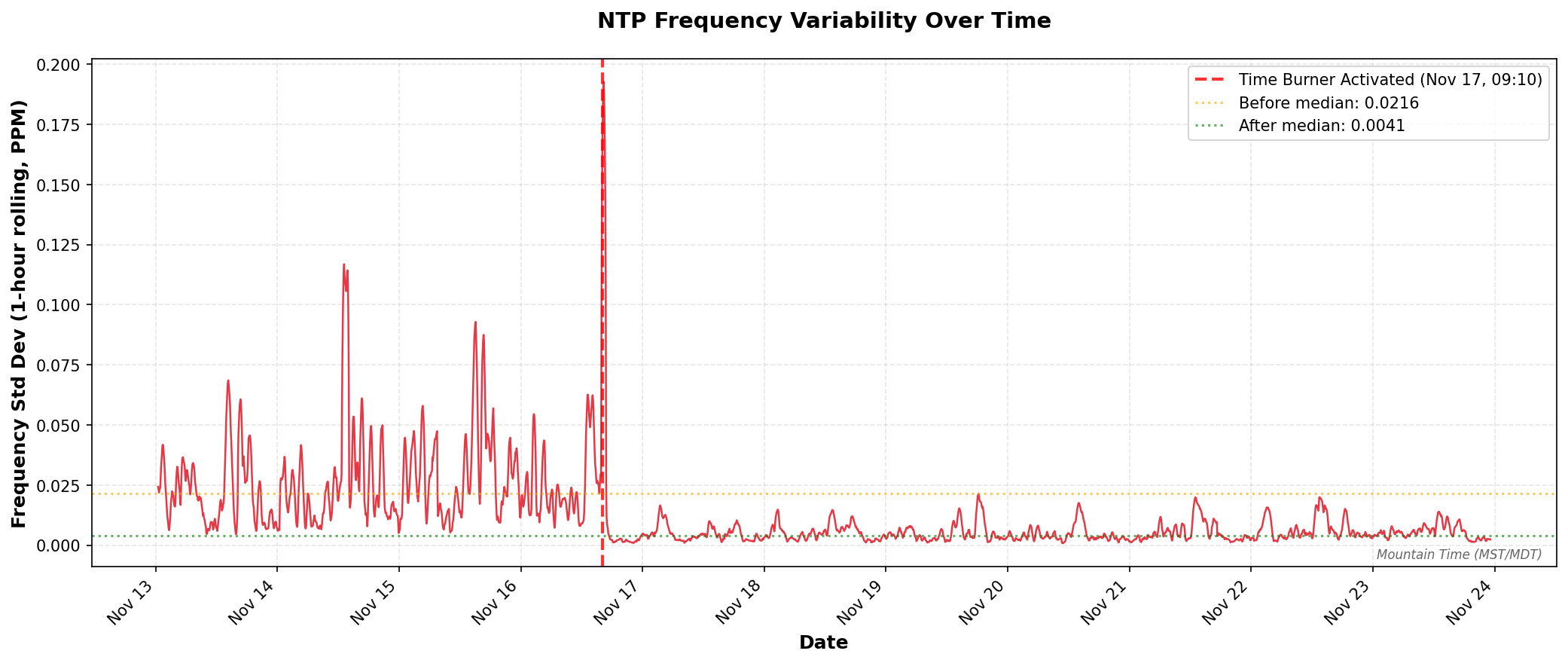
Here’s what happened when I turned on the thermal stabilization system on November 17, 2025 at 09:10 AM:
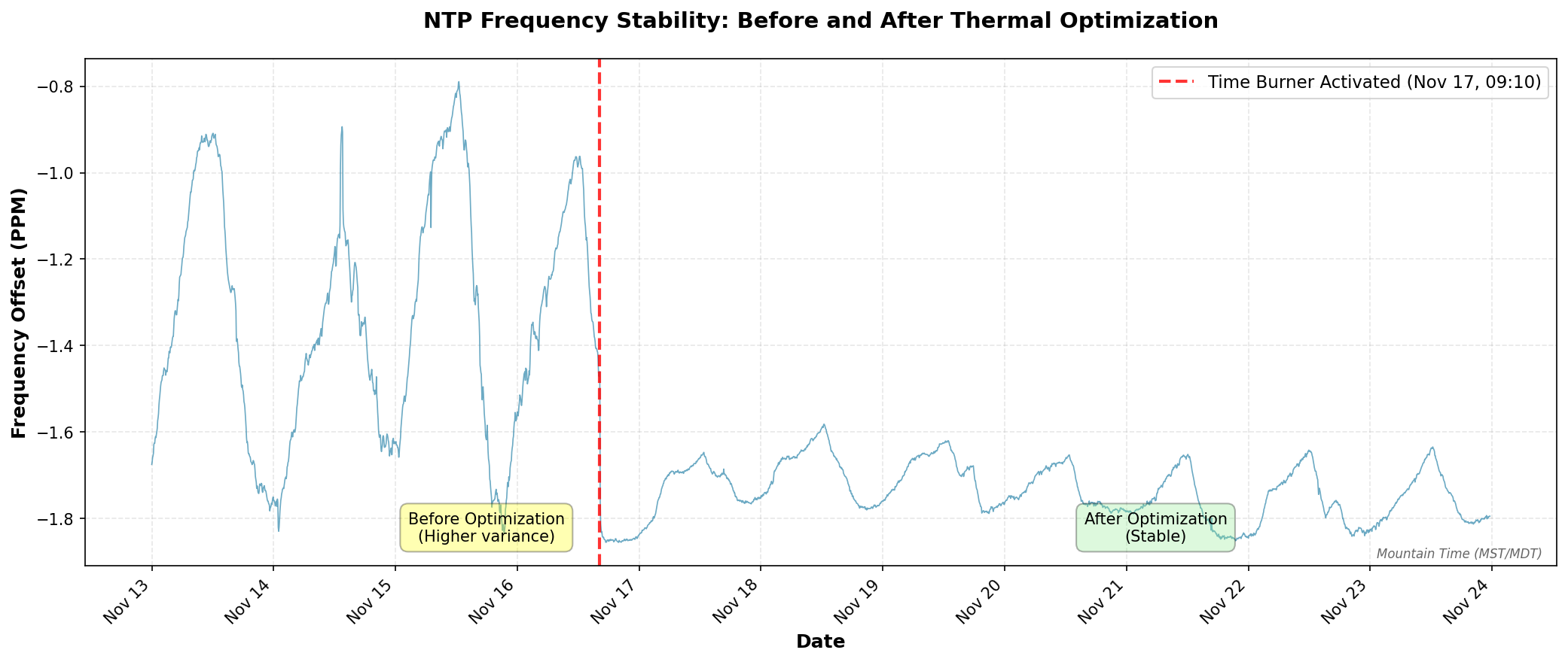
Same ish graph but with CPU temp also plotted:
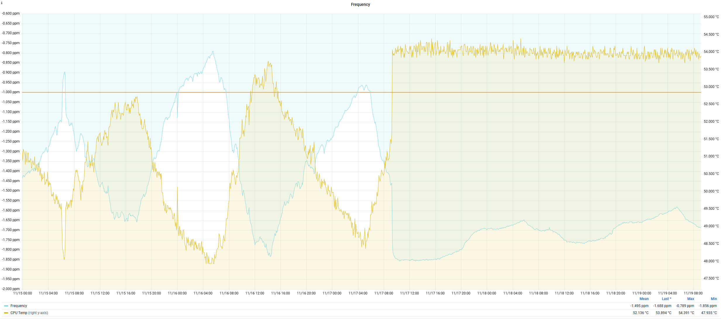
That vertical red line marks on the first plot when I activated the “time burner” process. Notice how the frequency oscillations immediately dampen and settle into a much tighter band? Let’s dive into how this works.
EDIT: 2025-11-25 I didn’t expect to wake up and see this at #2 on Hacker News – https://news.ycombinator.com/item?id=46042946
The Solution Part 1: CPU Core Pinning and Real-Time Priority
The first step is isolating timing-critical operations onto a dedicated CPU core. On a Raspberry Pi (4-core ARM), this means:
- CPU 0: Reserved for chronyd and PPS interrupts
- CPUs 1-3: Everything else, including our thermal load
I had AI (probably Claude Sonnet 4 ish, maybe 4.5) create a boot optimization script that runs at system startup:
#!/bin/bash
# PPS NTP Server Performance Optimization Script
# Sets CPU affinity, priorities, and performance governor at boot

set -e

echo "Setting up PPS NTP server performance optimizations..."

# Wait for system to be ready
sleep 5

# Set CPU governor to performance mode
echo "Setting CPU governor to performance..."
cpupower frequency-set -g performance

# Pin PPS interrupt to CPU0 (may fail if already pinned, that's OK)
echo "Configuring PPS interrupt affinity..."
echo 1 > /proc/irq/200/smp_affinity 2>/dev/null || echo "PPS IRQ already configured"

# Wait for chronyd to start
echo "Waiting for chronyd to start..."
timeout=30
while [ $timeout -gt 0 ]; do
    chronyd_pid=$(pgrep chronyd 2>/dev/null || echo "")
    if [ -n "$chronyd_pid" ]; then
        echo "Found chronyd PID: $chronyd_pid"
        break
    fi
    sleep 1
    ((timeout--))
done

if [ -z "$chronyd_pid" ]; then
    echo "Warning: chronyd not found after 30 seconds"
else
    # Set chronyd to real-time priority and pin to CPU 0
    echo "Setting chronyd to real-time priority and pinning to CPU 0..."
    chrt -f -p 50 $chronyd_pid
    taskset -cp 0 $chronyd_pid
fi

# Boost ksoftirqd/0 priority
echo "Boosting ksoftirqd/0 priority..."
ksoftirqd_pid=$(ps aux | grep '\[ksoftirqd/0\]' | grep -v grep | awk '{print $2}')
if [ -n "$ksoftirqd_pid" ]; then
    renice -n -10 $ksoftirqd_pid
    echo "ksoftirqd/0 priority boosted (PID: $ksoftirqd_pid)"
else
    echo "Warning: ksoftirqd/0 not found"
fi

echo "PPS NTP optimization complete!"

# Log current status
echo "=== Current Status ==="
echo "CPU Governor: $(cat /sys/devices/system/cpu/cpu0/cpufreq/scaling_governor)"
echo "PPS IRQ Affinity: $(cat /proc/irq/200/effective_affinity_list 2>/dev/null || echo 'not readable')"
if [ -n "$chronyd_pid" ]; then
    echo "chronyd Priority: $(chrt -p $chronyd_pid)"
fi
echo "======================"
What this does:
- Performance Governor: Forces all CPUs to run at maximum frequency, disabling frequency scaling
- PPS IRQ Pinning: Ensures PPS interrupt (IRQ 200) is handled exclusively by CPU 0
- Chronyd Real-Time Priority: Sets chronyd to SCHED_FIFO priority 50, giving it preferential CPU scheduling
- Chronyd CPU Affinity: Pins chronyd to CPU 0 using
taskset - ksoftirqd Priority Boost: Improves priority of the kernel softirq handler on CPU 0
This script can be added to /etc/rc.local or as a systemd service to run at boot.
The Solution Part 2: PID-Controlled Thermal Stabilization
Setting the performance governor helps, but on a Raspberry Pi, even at max frequency, the CPU temperature will still vary based on ambient conditions and load. Temperature changes affect the CPU’s actual operating frequency due to thermal characteristics of the silicon.
The solution? Keep the CPU at a constant temperature using a PID-controlled thermal load. I call it the “time burner” (inspired by CPU burn-in tools, but with precise temperature control).
As a reminder of what we’re really doing here: we’re maintaining a stable thermal environment for the crystal oscillator. The RPi 3B’s 19.2 MHz oscillator is physically located near the CPU on the Raspberry Pi board, so by actively controlling CPU temperature, we’re indirectly controlling the oscillator’s temperature. Since the oscillator’s frequency is temperature-dependent (this is basic physics of quartz crystals), keeping it at a constant temperature means keeping its frequency stable – which is exactly what we need for precise timekeeping.
Here’s how it works:
- Read CPU temperature from
/sys/class/thermal/thermal_zone0/temp - PID controller calculates how much CPU time to burn to maintain target temperature (I chose 54°C)
- Three worker processes run on CPUs 1, 2, and 3 (avoiding CPU 0)
- Each worker alternates between busy-loop (MD5 hashing) and sleeping based on PID output
- Temperature stabilizes at the setpoint, preventing thermal drift
Here’s the core implementation (simplified for readability):
#!/usr/bin/env python3
import time
import argparse
import multiprocessing
import hashlib
import os
from collections import deque

class PIDController:
    """Simple PID controller with output clamping and anti-windup."""
    def __init__(self, Kp, Ki, Kd, setpoint, output_limits=(0, 1), sample_time=1.0):
        self.Kp = Kp
        self.Ki = Ki
        self.Kd = Kd
        self.setpoint = setpoint
        self.output_limits = output_limits
        self.sample_time = sample_time
        self._last_time = time.time()
        self._last_error = 0.0
        self._integral = 0.0
        self._last_output = 0.0

    def update(self, measurement):
        """Compute new output of PID based on measurement."""
        now = time.time()
        dt = now - self._last_time

        if dt < self.sample_time:
            return self._last_output

        error = self.setpoint - measurement

        # Proportional
        P = self.Kp * error

        # Integral with anti-windup
        self._integral += error * dt
        I = self.Ki * self._integral

        # Derivative
        derivative = (error - self._last_error) / dt if dt > 0 else 0.0
        D = self.Kd * derivative

        # Combine and clamp
        output = P + I + D
        low, high = self.output_limits
        output = max(low, min(high, output))

        self._last_output = output
        self._last_error = error
        self._last_time = now

        return output

def read_cpu_temperature(path='/sys/class/thermal/thermal_zone0/temp'):
    """Return CPU temperature in Celsius."""
    with open(path, 'r') as f:
        temp_str = f.read().strip()
    return float(temp_str) / 1000.0

def burn_cpu(duration):
    """Busy-loop hashing for 'duration' seconds."""
    end_time = time.time() + duration
    m = hashlib.md5()
    while time.time() < end_time:
        m.update(b"burning-cpu")

def worker_loop(worker_id, cmd_queue, done_queue):
    """
    Worker process:
    - Pins itself to CPUs 1, 2, or 3 (avoiding CPU 0)
    - Burns CPU based on commands from main process
    """
    available_cpus = [1, 2, 3]
    cpu_to_use = available_cpus[worker_id % len(available_cpus)]
    os.sched_setaffinity(0, {cpu_to_use})
    print(f"Worker {worker_id} pinned to CPU {cpu_to_use}")

    while True:
        cmd = cmd_queue.get()
        if cmd is None:
            break

        burn_time, sleep_time = cmd
        burn_cpu(burn_time)
        time.sleep(sleep_time)
        done_queue.put(worker_id)

# Main control loop (simplified)
def main():
    target_temp = 54.0  # degrees Celsius
    control_window = 0.20  # 200ms cycle time

    pid = PIDController(Kp=0.05, Ki=0.02, Kd=0.0,
                        setpoint=target_temp,
                        sample_time=0.18)

    # Start 3 worker processes
    workers = []
    cmd_queues = []
    done_queue = multiprocessing.Queue()

    for i in range(3):
        q = multiprocessing.Queue()
        p = multiprocessing.Process(target=worker_loop, args=(i, q, done_queue))
        p.start()
        workers.append(p)
        cmd_queues.append(q)

    try:
        while True:
            # Measure temperature
            current_temp = read_cpu_temperature()

            # PID control: output is fraction of time to burn (0.0 to 1.0)
            output = pid.update(current_temp)

            # Convert to burn/sleep times
            burn_time = output * control_window
            sleep_time = control_window - burn_time

            # Send command to all workers
            for q in cmd_queues:
                q.put((burn_time, sleep_time))

            # Wait for workers to complete
            for _ in range(3):
                done_queue.get()

            print(f"Temp={current_temp:.2f}C, Output={output:.2f}, "
                  f"Burn={burn_time:.2f}s")

    except KeyboardInterrupt:
        for q in cmd_queues:
            q.put(None)
        for p in workers:
            p.join()

if __name__ == '__main__':
    main()
The full implementation includes a temperature filtering system to smooth out sensor noise and command-line arguments for tuning the PID parameters.
PID Tuning Notes:
- Kp=0.05: Proportional gain – responds to current error
- Ki=0.02: Integral gain – eliminates steady-state error
- Kd=0.0: Derivative gain – set to zero because temperature changes slowly
The target temperature of 54°C was chosen empirically – high enough to keep the CPU from idling down, but low enough to avoid thermal throttling (which starts around 80°C on Raspberry Pi).
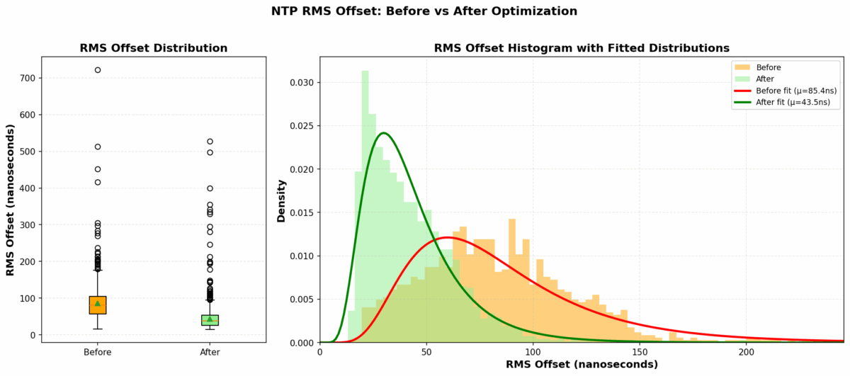
The Results: Numbers Don’t Lie
The improvement was immediately visible. Here are the statistics comparing performance before and after the optimization:
A note on ambient conditions: The Raspberry Pi lives in a project enclosure in our master bedroom (chosen for its decent GPS reception and ADS-B coverage for a new aircraft AR overlay app idea I’m working on also running on this Pi). While the time burner maintains the CPU die temperature at 54°C, the enclosure is still subject to ambient temperature swings. Room temperature cycles from a low of 66°F (18.9°C) at 5:15 AM to a peak of 72°F (22.2°C) at 11:30 AM – a 6°F daily swing from our heating schedule. The fact that we see such dramatic frequency stability improvements despite this ambient variation speaks to how effective the thermal control is. The CPU’s active heating overwhelms the environmental changes, maintaining consistent silicon temperature where it matters most.
Frequency Stability
| Metric | Before | After | Improvement |
|---|---|---|---|
| Mean RMS Offset | 85.44 ns | 43.54 ns | 49.0% reduction |
| Median RMS Offset | 80.13 ns | 37.93 ns | 52.7% reduction |
The RMS offset is chronyd’s estimate of the timing uncertainty. Cutting this nearly in half means the system is maintaining significantly better time accuracy.
Setup Instructions
Want to replicate this? Here’s the step-by-step process:
Prerequisites
You need a working GPS PPS NTP server setup. If you don’t have one yet, follow my 2025 NTP guide first.
Step 0: Install Required Tools
sudo apt-get update
sudo apt-get install linux-cpupower python3 util-linux
Step 1: Create the Boot Optimization Script
Save the optimization script from earlier as /usr/local/bin/pps-optimize.sh:
sudo nano /usr/local/bin/pps-optimize.sh
# Paste the script content
sudo chmod +x /usr/local/bin/pps-optimize.sh
Step 2: Create Systemd Service for Boot Script
Create /etc/systemd/system/pps-optimize.service:
[Unit]
Description=PPS NTP Performance Optimization
After=chronyd.service
Requires=chronyd.service

[Service]
Type=oneshot
ExecStart=/usr/local/bin/pps-optimize.sh
RemainAfterExit=yes

[Install]
WantedBy=multi-user.target
Enable it:
sudo systemctl enable pps-optimize.serviceStep 3: Install the Time Burner Script
Save the time burner Python script as /usr/local/bin/time_burner.py:
sudo nano /usr/local/bin/time_burner.py
# Paste the full time burner script
sudo chmod +x /usr/local/bin/time_burner.py
Step 4: Create Systemd Service for Time Burner
Create /etc/systemd/system/time-burner.service:
[Unit]
Description=CPU Thermal Stabilization for NTP
After=network.target

[Service]
Type=simple
User=root
ExecStart=/usr/bin/python3 /usr/local/bin/time_burner.py -t 54.0 -n 3
Restart=always
RestartSec=10

[Install]
WantedBy=multi-user.target
Enable and start it:
sudo systemctl enable time-burner.service
sudo systemctl start time-burner.service
Step 5: Verify the Setup
Check that everything is running:
# Verify CPU governor
cat /sys/devices/system/cpu/cpu0/cpufreq/scaling_governor
# Should output: performance

# Check chronyd CPU affinity and priority
ps -eo pid,comm,psr,ni,rtprio | grep chronyd
# Should show psr=0 (CPU 0) and rtprio=50

# Check time burner processes
ps aux | grep time_burner
# Should show 4 processes (1 main + 3 workers)

# Monitor NTP performance
chronyc tracking
Example output from chronyc tracking:
Reference ID    : 50505300 (PPS)
Stratum         : 1
Ref time (UTC)  : Sun Nov 24 16:45:23 2025
System time     : 0.000000038 seconds fast of NTP time
Last offset     : -0.000000012 seconds
RMS offset      : 0.000000035 seconds
Frequency       : 1.685 ppm slow
Residual freq   : -0.001 ppm
Skew            : 0.002 ppm
Root delay      : 0.000000001 seconds
Root dispersion : 0.000010521 seconds
Update interval : 16.0 seconds
Leap status     : Normal
Notice the RMS offset of 35 nanoseconds – this is the kind of accuracy you can achieve with thermal stabilization.
Step 6: Monitor Over Time
(Topic for a future post)
Set up Grafana dashboards to monitor:
- Frequency offset (PPM)
- RMS offset (nanoseconds)
- CPU temperature
- System time offset
You’ll see the frequency stabilize within a few hours as the PID controller locks onto the target temperature.
Monitoring and Troubleshooting
Real-Time Monitoring
Watch chronyd tracking in real-time:
watch -n 1 "chronyc tracking"Check time burner status:
sudo systemctl status time-burner.serviceView time burner output:
sudo journalctl -u time-burner.service -fCommon Issues
Temperature overshoots or oscillates:
- Adjust PID gains – reduce Kp if oscillating, increase Ki if steady-state error
- Try different target temperatures (50-60°C range)
High CPU usage (obviously):
- This is intentional – the time burner uses ~90% of 3 cores
- Not suitable for Pis running other workloads
Chronyd not pinned to CPU 0:
- Check that the optimization script runs after chronyd starts
- Adjust the timing in the systemd service dependencies
Trade-offs and Considerations
Let’s be honest about the downsides:
Power Consumption
The time burner keeps 3 cores at ~30% average utilization. My Pi now draws about 3-4W continuously (vs 1-2W idle). Over a year, that’s an extra 15-25 kWh, or about $2-3 in electricity (depending on your rates).
Heat
Running at 54°C means the Pi is warm to the touch. This is well within safe operating temperature (thermal throttling doesn’t start until 80°C), but you might want to ensure adequate ventilation. I added a small heatsink just to be safe.
CPU Resources
You’re dedicating 3 of 4 cores to burning cycles. This is fine for a dedicated NTP server, but not suitable if you’re running other services on the same Pi. That said, I am also running the feeder to my new ADS-B aircraft visualization app on it. My readsb instance regularly gets to 1200 msg/s with 200+ aircraft.
Is It Worth It?
For 99.999% of use cases: absolutely not.
Most applications don’t need better than millisecond accuracy, let alone the 35-nanosecond RMS offset I’m achieving. Even for distributed systems, microsecond-level accuracy is typically overkill.
When this might make sense:
- Precision timing applications (scientific instrumentation, radio astronomy)
- Distributed systems research requiring tight clock synchronization
- Network testing where timing precision affects results
- Because you can (the best reason for any homelab project)
For me, this falls squarely in the “because you can” category. I had the monitoring infrastructure in place, noticed the thermal correlation, and couldn’t resist solving the problem. Plus, I learned a lot about PID control, CPU thermal characteristics, and Linux real-time scheduling.
Future Improvements
Some ideas I’m considering:
Adaptive PID Tuning
The current PID gains are hand-tuned for a specific ambient temperature range. The fairly low P value is to avoid spikes when some load on the Pi kicks up the temp. The I is a balance to keep long term “burn” relatively consistent. Implementing an auto-tuning algorithm (like Ziegler-Nichols) or adaptive PID could handle seasonal temperature variations better.
Hardware Thermal Control
Instead of software thermal control, I could add an actively cooled heatsink with PWM fan control. This might achieve similar temperature stability while using less power overall.
Oven-Controlled Crystal Oscillator (OCXO)
For the ultimate in frequency stability, replacing the Pi’s crystal with a temperature-controlled OCXO would eliminate thermal drift at the source. This is how professional timing equipment works. I do have a BH3SAP GPSDO sitting next to me (subject to a future post)… Then again, I’m the person who just wrote 4000 words about optimizing a $50 time server, so who am I kidding?
Conclusions
Through a combination of CPU core isolation and PID-controlled thermal stabilization, I achieved:
- 81% reduction in frequency variability
- 77% reduction in frequency standard deviation
- 74% reduction in frequency range
- 49% reduction in RMS offset
The system now maintains 38-nanosecond median RMS offset from the GPS PPS reference, with frequency drift that’s barely detectable in the noise. The CPU runs at a constant 54°C, and in steady state, the frequency offset stays within a tight ±0.14 PPM band (compared to ±0.52 PPM before optimization).
Was this necessary? No. Did I learn a bunch about thermal management, PID control, and Linux real-time scheduling? Yes. Would I do it again? Absolutely.
Resource
I did come across a “burn” script that was the basis for this thermal management. I can’t find it at the moment, but when I do I’ll link it here.
Related Posts
- Microsecond-Accurate NTP with a Raspberry Pi and PPS GPS (2021)
- Revisiting Microsecond-Accurate NTP for Raspberry Pi in 2025
Further Reading
Have questions or suggestions? Drop a comment below. I’m particularly interested to hear if anyone has tried alternative thermal management approaches or has experience with OCXO modules for Raspberry Pi timing applications.
Thanks for reading, and happy timekeeping!