
Introduction
Lots of acronyms in that title. If I expand them out, it says – “microsecond accurate network time protocol with a Raspberry Pi and pulse per second global positioning system [receiver]”. What it means is you can get super accurate timekeeping (1 microsecond = 0.000001 seconds) with a Raspberry Pi and a GPS receiver (the GT-U7 is less than $12) that spits out pulses every second. By following this guide, you will your very own Stratum 1 NTP server at home!
2025 Update – I wrote a new post with some newer best practices and guidance for 2025, including how to synchronize machines with nanosecond precision using PTP (precision time protocol). Read that post first then come back here – not all discussion is in both places.
Why would you need time this accurate at home?
You don’t. There aren’t many applications for this level of timekeeping in general, and even fewer at home. But this blog is called Austin’s Nerdy Things so here we are. Using standard, default internet NTP these days will get your computers to within a 10-20 milliseconds of actual time (1 millisecond = 0.001 seconds). By default, Windows computers get time from time.windows.com. MacOS computers get time from time.apple.com. Linux devices get time from [entity].pool.ntp.org, like debian.pool.ntp.org. PPS gets you to the next SI prefix in terms of accuracy (milli -> micro), which means 1000x more accurate timekeeping.
YouTube video link
If you prefer a video version – https://www.youtube.com/watch?v=YfgX7qPeiqQ
Materials needed
- Raspberry Pi (either the 3 or the 4 will work)
- GPS with PPS output – Adafruit Ultimate GPS ($40ish) or the GT-U7 ($12ish)
- (optional) – a GPS antenna (for getting better GPS satellite reception)
- Wires to connect it all up (5 wires needed – 5V/RX/TX/GND/PPS)
- 15-30 minutes
Steps
0 – Update your Pi and install packages
This NTP guide assumes you have a Raspberry Pi ready to go. If you don’t, I have a 16 minute video on YouTube that goes through flashing the SD card and initial setup – https://youtu.be/u5dHvEYwr9M.
You should update your Pi to latest before basically any project. We will install some other packages as well. pps-tools help us check that the Pi is receiving PPS signals from the GPS module. We also need GPSd for the GPS decoding of both time and position. I use chrony instead of NTPd because it seems to sync faster than NTPd in most instances and also handles PPS without compiling from source (the default Raspbian NTP doesn’t do PPS) Installing chrony will remove ntpd.
sudo apt update
sudo apt upgrade
sudo rpi-update
sudo apt install pps-tools gpsd gpsd-clients python-gps chrony
1 – add GPIO and module info where needed
In /boot/config.txt, add ‘dtoverlay=pps-gpio,gpiopin=18’ to a new line. This is necessary for PPS. If you want to get the NMEA data from the serial line, you must also enable UART and set the initial baud rate.
sudo bash -c "echo '# the next 3 lines are for GPS PPS signals' >> /boot/config.txt"
sudo bash -c "echo 'dtoverlay=pps-gpio,gpiopin=18' >> /boot/config.txt"
sudo bash -c "echo 'enable_uart=1' >> /boot/config.txt"
sudo bash -c "echo 'init_uart_baud=9600' >> /boot/config.txt"
In /etc/modules, add ‘pps-gpio’ to a new line.
sudo bash -c "echo 'pps-gpio' >> /etc/modules"
Reboot
sudo reboot
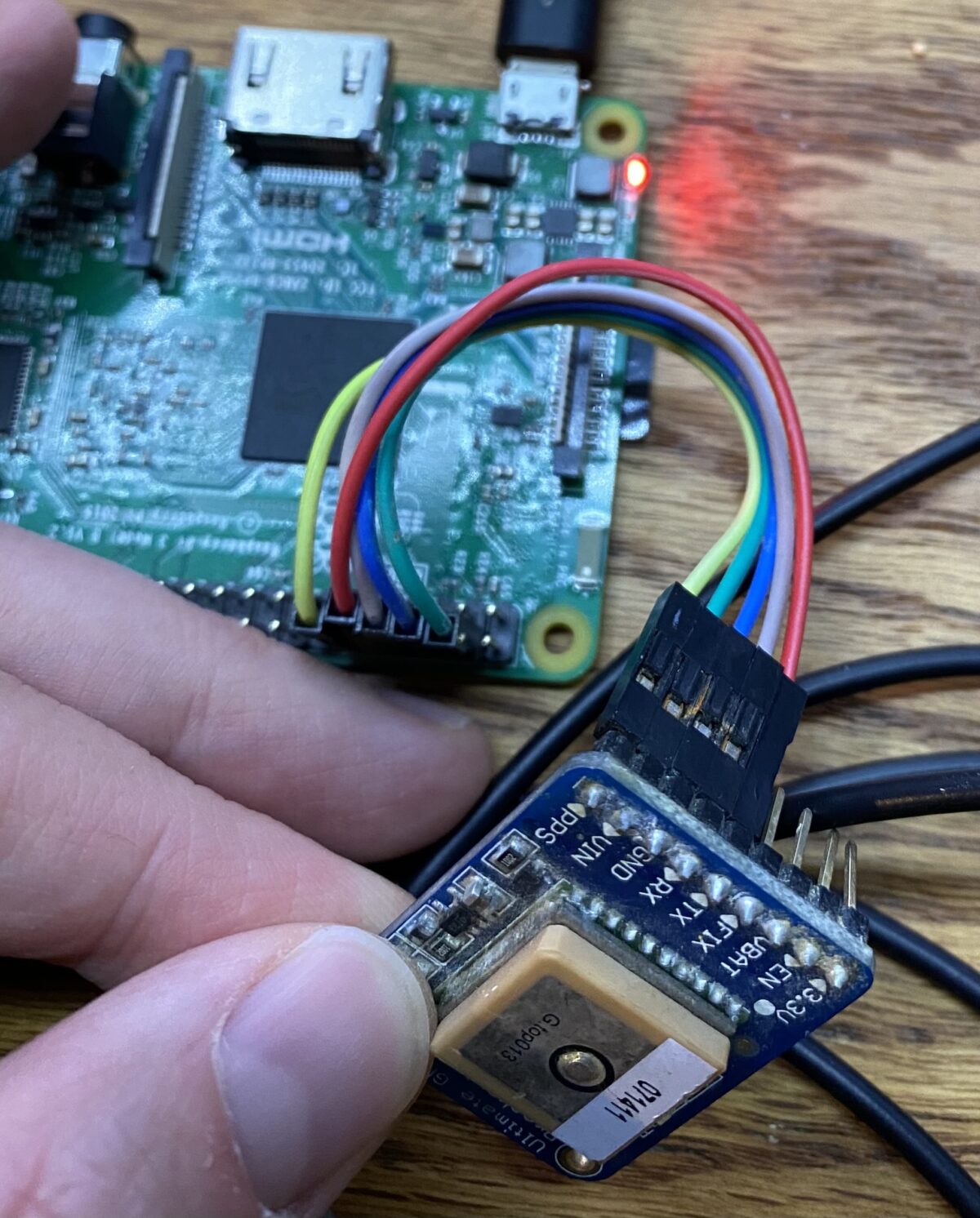
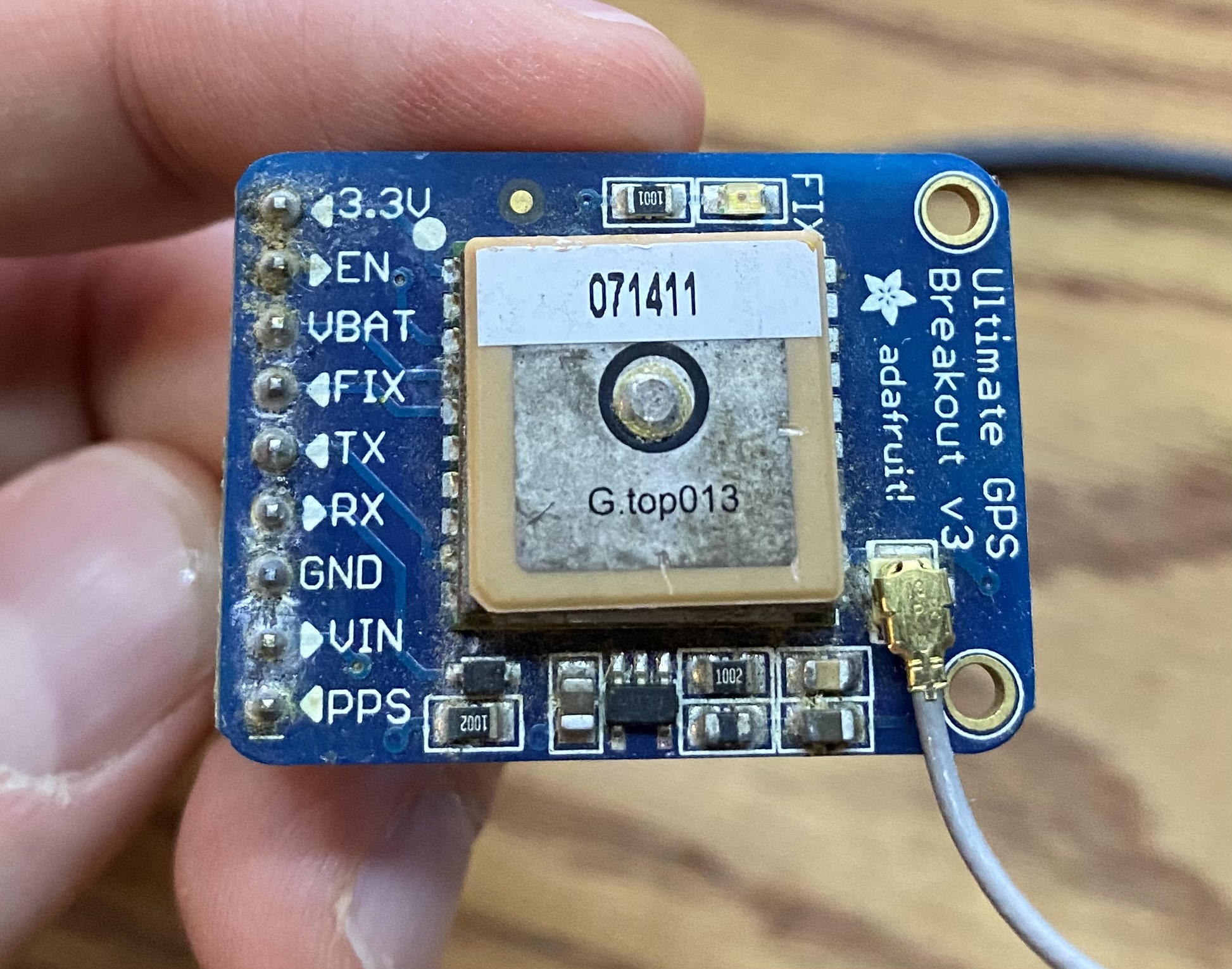
2 – wire up the GPS module to the Pi
I used the Adafruit Ultimate GPS breakout. It has 9 pins but we are only interested in 5. There is also the Adafruit GPS hat which fits right on the Pi but that seems expensive for what it does (but it is significantly neater in terms of wiring).
Pin connections:
- GPS PPS to RPi pin 12 (GPIO 18)
- GPS VIN to RPi pin 2 or 4
- GPS GND to RPi pin 6
- GPS RX to RPi pin 8
- GPS TX to RPi pin 10
- see 2nd picture for a visual

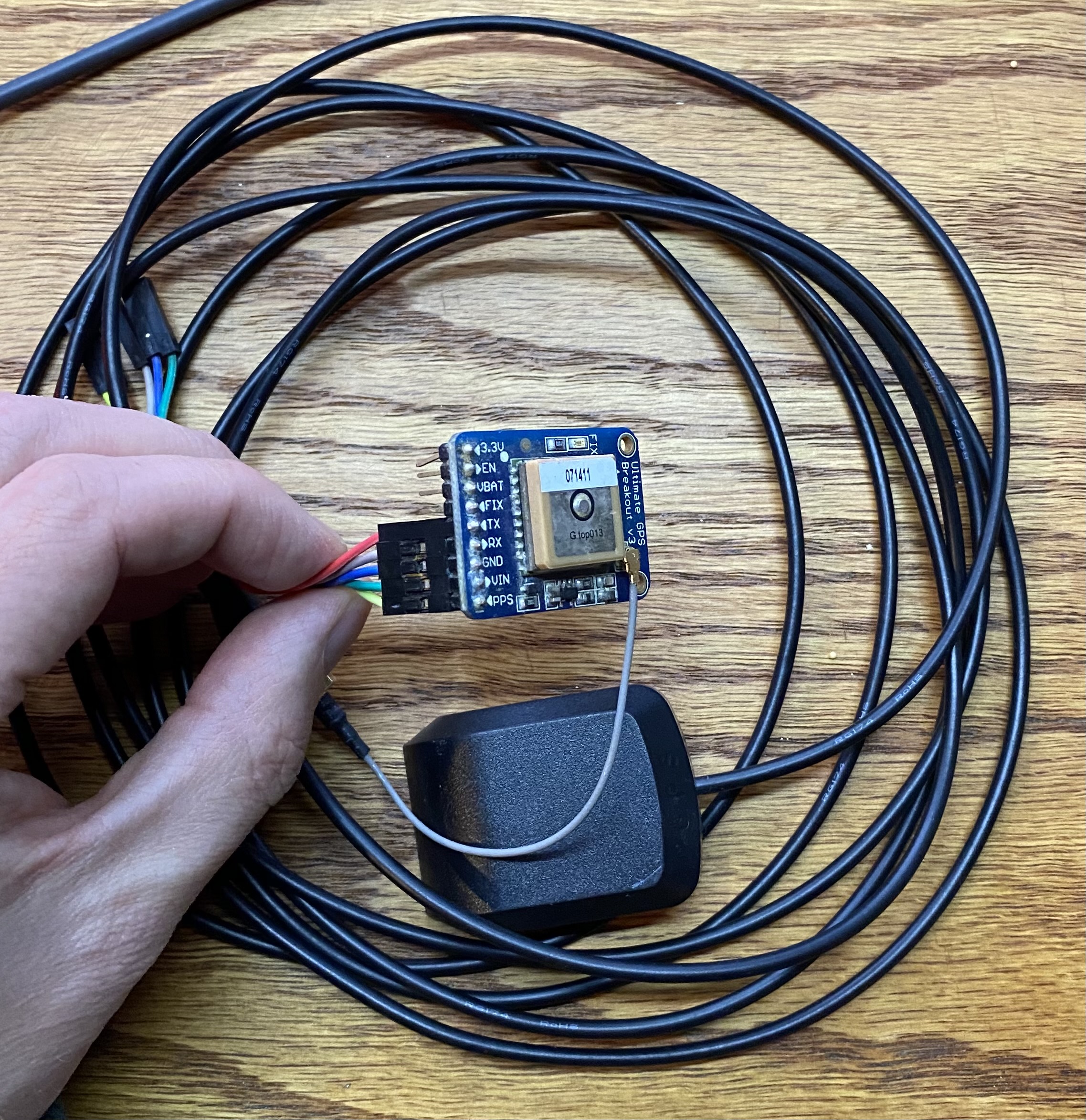
Now place your GPS antenna (if you have one) in a spot with a good view of the sky. If you don’t have an antenna, you might have to get a bit creative with how you locate your Raspberry Pi with attached GPS.
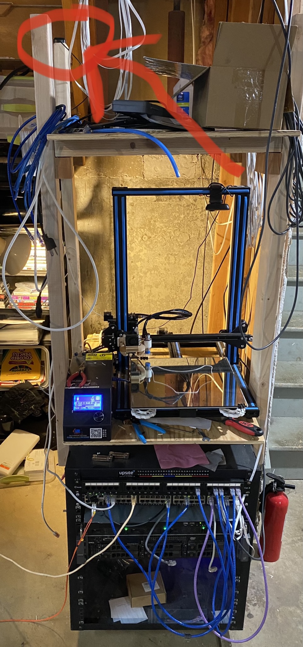
I honestly have my antenna in the basement (with only the kitchen and attic above) and I generally have 8-10 satellites locked all the time (11 as of writing). Guess that means the antenna works better than expected! Either way, better exposure to the sky will in theory work better. Pic:
2.5 – free up the UART serial port for the GPS device
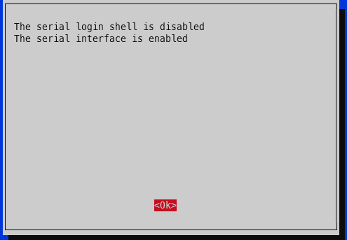
Run raspi-config -> 3 – Interface options -> I6 – Serial Port -> Would you like a login shell to be available over serial -> No. -> Would you like the serial port hardware to be enabled -> Yes.
Finish. Yes to reboot.
3 – check that PPS is working
First, check that the PPS module is loaded:
lsmod | grep pps
The output should be like:
pi@raspberrypi:~ $ lsmod | grep pps
pps_gpio               16384  0
pps_core               16384  1 pps_gpio
Second, check for the PPS pulses:
sudo ppstest /dev/pps0
The output should spit out a new line every second that looks something like this (your output will be a bit farther from x.000000 since it isn’t yet using the GPS PPS):
pi@pi-ntp:~ $ sudo ppstest /dev/pps0
trying PPS source "/dev/pps0"
found PPS source "/dev/pps0"
ok, found 1 source(s), now start fetching data...
source 0 - assert 1618799061.999999504, sequence: 882184 - clear  0.000000000, sequence: 0
source 0 - assert 1618799062.999999305, sequence: 882185 - clear  0.000000000, sequence: 0
source 0 - assert 1618799063.999997231, sequence: 882186 - clear  0.000000000, sequence: 0
source 0 - assert 1618799064.999996827, sequence: 882187 - clear  0.000000000, sequence: 0
source 0 - assert 1618799065.999995852, sequence: 882188 - clear  0.000000000, sequence: 0
^C
4 – change GPSd to start immediately upon boot
Edit /etc/default/gpsd and change GPSD_OPTIONS=”” to GPSD_OPTIONS=”-n” and change DEVICES=”” to DEVICES=”/dev/ttyS0 /dev/pps0″, then reboot. My full /etc/default/gpsd is below:
pi@raspberrypi:~ $ sudo cat /etc/default/gpsd
# Default settings for the gpsd init script and the hotplug wrapper.

# Start the gpsd daemon automatically at boot time
START_DAEMON="true"

# Use USB hotplugging to add new USB devices automatically to the daemon
USBAUTO="true"

# Devices gpsd should collect to at boot time.
# They need to be read/writeable, either by user gpsd or the group dialout.
DEVICES="/dev/ttyS0 /dev/pps0"

# Other options you want to pass to gpsd
GPSD_OPTIONS="-n"
sudo reboot
4.5 – check GPS for good measure
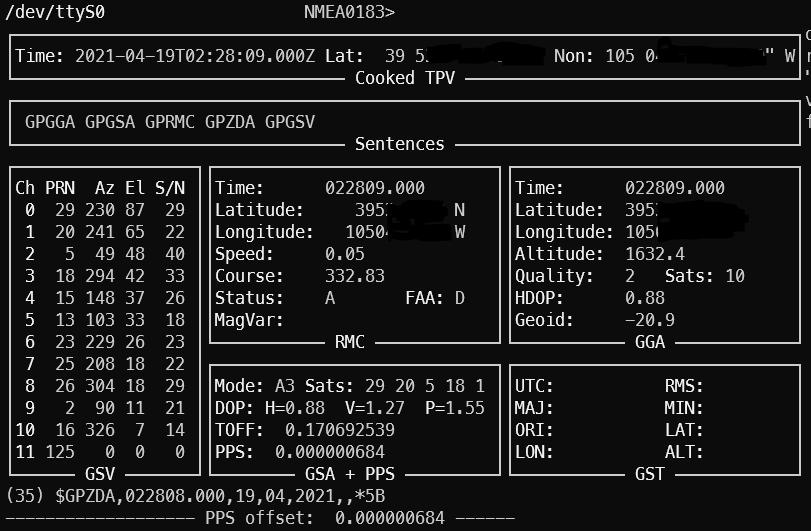
To ensure your GPS has a valid position, you can run gpsmon or cgps to check satellites and such. This check also ensures GPSd is functioning as expected. If your GPS doesn’t have a position solution, you won’t get a good time signal. If GPSd isn’t working, you won’t get any updates on the screen. The top portion will show the analyzed GPS data and the bottom portion will scroll by with the raw GPS sentences from the GPS module.
5 – edit config files
For chrony, add these two lines to the /etc/chrony/chrony.conf file somewhere near the rest of the server lines:
refclock SHM 0 refid NMEA offset 0.200
refclock PPS /dev/pps0 refid PPS lock NMEA
2025 update: see the newer post chrony config for how to get single source (i.e. just your single GPS to use both NMEA and PPS) timing to works successfully.
My entire /etc/chrony/chrony.conf file looks like this:
###### below this line are custom config changes #######
server 10.98.1.1 iburst minpoll 3 maxpoll 5
server time-a-b.nist.gov iburst
server time-d-b.nist.gov
server utcnist.colorado.edu
server time.windows.com
server time.apple.com

# delay determined experimentally by setting noselect then monitoring for a few hours
# 0.325 means the NMEA time sentence arrives 325 milliseconds after the PPS pulse
# the delay adjusts it forward
refclock SHM 0 delay 0.325 refid NMEA
refclock PPS /dev/pps0 refid PPS

allow 10.98.1.0/24 # my home network
###### above this line are custom config changes #######

###### below this line is standard chrony stuff #######
keyfile /etc/chrony/chrony.keys
driftfile /var/lib/chrony/chrony.drift
#log tracking measurements statistics
logdir /var/log/chrony
maxupdateskew 100.0
hwclockfile /etc/adjtime
rtcsync
makestep 1 3
Restart chrony, wait a few minutes, and verify.
sudo systemctl restart chrony
5 – verify the NTP server is using the GPS PPS
Right after a chrony restart, the sources will look like this (shown by running ‘chronyc sources’)
pi@pi-ntp:~ $ chronyc sources
210 Number of sources = 9
MS Name/IP address         Stratum Poll Reach LastRx Last sample
===============================================================================
#? NMEA                          0   4     0     -     +0ns[   +0ns] +/-    0ns
#? PPS                           0   4     0     -     +0ns[   +0ns] +/-    0ns
^? pfsense.home.fluffnet.net     0   3     3     -     +0ns[   +0ns] +/-    0ns
^? time-a-b.nist.gov             1   6     3     1  -2615us[-2615us] +/- 8218us
^? time-d-b.nist.gov             1   6     1     3  -2495us[-2495us] +/- 7943us
^? india.colorado.edu            0   6     0     -     +0ns[   +0ns] +/-    0ns
^? 13.86.101.172                 3   6     1     4  -4866us[-4866us] +/-   43ms
^? usdal4-ntp-002.aaplimg.c>     1   6     1     4  -2143us[-2143us] +/-   13ms
^? time.cloudflare.com           3   6     1     3  -3747us[-3747us] +/- 9088us
The # means locally connected source of time. The question marks mean it is still determine the status of each source.
After a couple minutes, you can check again:
pi@pi-ntp:~ $ chronyc -n sources
210 Number of sources = 9
MS Name/IP address         Stratum Poll Reach LastRx Last sample
===============================================================================
#x NMEA                          0   4   377    23    -37ms[  -37ms] +/- 1638us
#* PPS                           0   4   377    25   -175ns[ -289ns] +/-  126ns
^? 10.98.1.1                     0   5   377     -     +0ns[   +0ns] +/-    0ns
^- 132.163.96.1                  1   6   177    22  -3046us[-3046us] +/- 8233us
^- 2610:20:6f96:96::4            1   6    17    28  -2524us[-2524us] +/- 7677us
^? 128.138.140.44                1   6     3    30  -3107us[-3107us] +/- 8460us
^- 13.86.101.172                 3   6    17    28  -8233us[-8233us] +/-   47ms
^- 17.253.2.253                  1   6    17    29  -3048us[-3048us] +/-   14ms
^- 2606:4700:f1::123             3   6    17    29  -3325us[-3325us] +/- 8488us
For the S column, * means the source that is active. + means it is considered a good source and would be used if the current one is determined to be bad or is unavailable. The x shown for the NMEA source means it is a “false ticker”, which means it isn’t being used. In our case that is fine because the PPS source is active and valid. Anything else generally means it won’t be used.
In this case, chrony is using the PPS signal. The value inside the brackets is how far off chrony is from the source. It is showing that we are 289 nanoseconds off of GPS PPS time. This is very, very close to atomic clock level accuracy. The last column (after the +/-) includes latency to the NTP source as well as how far out of sync chrony thinks it is (for example, the 17.253.2.253 server is 12.5 milliseconds away one-way via ping):
pi@pi-ntp:~ $ ping -c 5 17.253.2.253
PING 17.253.2.253 (17.253.2.253) 56(84) bytes of data.
64 bytes from 17.253.2.253: icmp_seq=1 ttl=54 time=25.2 ms
64 bytes from 17.253.2.253: icmp_seq=2 ttl=54 time=27.7 ms
64 bytes from 17.253.2.253: icmp_seq=3 ttl=54 time=23.8 ms
64 bytes from 17.253.2.253: icmp_seq=4 ttl=54 time=24.4 ms
64 bytes from 17.253.2.253: icmp_seq=5 ttl=54 time=23.4 ms

--- 17.253.2.253 ping statistics ---
5 packets transmitted, 5 received, 0% packet loss, time 4007ms
rtt min/avg/max/mdev = 23.403/24.954/27.780/1.547 ms
For a full list of information about how to interpret these results, check here – https://docs.fedoraproject.org/en-US/Fedora/18/html/System_Administrators_Guide/sect-Checking_if_chrony_is_synchronized.html
6 – results
A day after the bulk of writing this post, I turned on logging via the .conf file and restarted chrony. It settled to microsecond level accuracy in 57 seconds. For the offset column, the scientific notation e-7 means the results are in nanoseconds. This means that for the 19:54:35 line, the clock is -450.9 nanoseconds off of the PPS signal. There is that e-10 line in there which says that it is 831 picoseconds off PPS (I had to look up SI prefixes to make sure pico came after nano! also I doubt the Pi can actually keep track of time that closely.). After the initial sync, there is only 1 line in the below log that is actually at the microsecond level (the others are all better than microsecond) – the 20:00:59 entry, which shows the clock is -1.183 microseconds off.
Things that affect timekeeping on the Pi
Thought I’d toss in this section for completeness (i.e. thanks for all the good info Austin but how can I make this even better?). There are a few things that affect how well the time is kept on the Pi:
- Ambient temperature around the Pi – if you plot the freq PPM against ambient temperature, there will be a clear trend. The more stable the ambient temp, the less variation in timekeeping.
- Load on the Pi – similar to above. Highly variable loads will make the processor work harder and easier. Harder working processor means more heat. More heat means more variability. These crystals are physical devices after all.
- GPS reception – they actually making timing GPS chips that prefer satellites directly overhead. They have better ability to filter out multipathing and such. In general, the better the GPS reception, the better the PPS signal.
Conclusion
After running through the steps in this guide, you should now have a functional Stratum 1 NTP server running on your Raspberry Pi with microsecond level accuracy provided by a PPS GPS. This system can obtain time in the absence of any external sources other than the GPS (for example, internet time servers), and then sync up with the extremely precise GPS PPS signal. Our NTP GPS PPS clock is now within a few microseconds of actual GPS time.
Update 2024-01-19: RIP Dave Mills, inventor/creator of NTP – https://arstechnica.com/gadgets/2024/01/inventor-of-ntp-protocol-that-keeps-time-on-billions-of-devices-dies-at-age-85/
Update 2025-11-25: See here for how to do some thermal management to improve the stability by a factor of at least 2x: https://austinsnerdythings.com/2025/11/24/worlds-most-stable-raspberry-pi-81-better-ntp-with-thermal-management/
References
I read a ton on https://www.satsignal.eu/ntp/Raspberry-Pi-NTP.html and other pages on that domain over the years which has been extremely helpful in getting GPS PPS NTP going for my setup. There is a lot of background info for how/why this stuff works and many useful graphics. Another source is https://wellnowweknow.com/index.php/2019/12/27/how-to-ntp-a-raspberry-pi-4-via-gps-and-pps/ for a short and sweet (maybe too short) set of commands.
Disclosure: When you click on links to various merchants in this post and make a purchase, this can result in this site earning a commission. Affiliate programs and affiliations include, but are not limited to, the eBay Partner Network.
95 replies on “Microsecond accurate NTP with a Raspberry Pi and PPS GPS”
You can make your Rasperry Pi considerable more accurate by replacing the current unregulated 19.2MHz crystal oscillator by a 19.2MHz TCXO. Doing that will reduce your clock jitter from hundred of nanoseconds to single digit nanoseconds over longer periods.
I would be interested in learning more about this. Can you tell me if its replacing the oscillator on the board or by connecting the new one through GPIO?
If you decide to by the Adafruit Ultimate GPS Pi Hat instead (which I did) you will need to change line 2 in step 1’s code from:
sudo bash -c “echo ‘dtoverlay=pps-gpio,gpiopin=18’ >> /boot/config.txt”
to
sudo bash -c “echo ‘dtoverlay=pps-gpio,gpiopin=4’ >> /boot/config.txt”
as the hat uses GPIO 4 for the pps.
Trying to get this to work with an Uputronics GPS/RTS board and can’t get anything out of it … uses the i2c bus which Raspberry apparently supports but trying to get any NMEA data out of it continues to be a mystery
What uputronics board? I was reading about some a week or two ago and I believe only the RTC portion is over the i2c bus. The GPS stuff is all still on serial.
https://store.uputronics.com/index.php?route=product/product&path=60_64&product_id=81
I figured out the details and listed them on a post further down …
Thanks for the nice tutorial.
I was able to make it kind of work with a rather cheap M6N receiver, that sends NMEA messages (could also easily read the messages using the “cat /dev/ttyS0” command, cpgs showed believable values). Kind of work, because chronyc sources picked the NMEA as the source, not the pps.
Trying to use a Sparkfun M9N chip, I was not able to make it work. cgps only dispalys Lat and Lon if I am lucky and chronyc sources marked both, NMEA and pps, with and “x”.
I have the suspicion, that it has to do with the protocol (“cat /dev/ttyS0” only shows gibberish, but in a nice pace). Can you give me a hint how to make it work using this GPS-receiver?
[…] off my last NTP post (Microsecond accurate NTP with a Raspberry Pi and PPS GPS), which required a $50-60 GPS device and a Raspberry Pi (also $40+), I have successfully tested […]
One might need to also stop the serial getty on /dev/ttyS0 to get gpsmon working. If you are having trouble with gpsmon not outputting valid information try:
systemctl disable [email protected]
systemctl stop [email protected]
Then restart gpsd with:
systemctl restart gpsd
And that might solve it…
Given there are some issues with the supply of RPi4 at the moment. Can this NTP server be created on an RPi2 as an alternative?
Yes it can! I believe it will work on any generation of a Pi. The loads of NTP are quite low. But if you want to try it on a 1/2 I wouldn’t put much else on it.
The rPI-2 uses MUCH much much less power, is multicore, and much more capable overall than a rPi/rPi-zero in this role. Doesn’t need a fan either. The newer zero-2w would be a more up to date platform, but home NTP servers are just make, put on the network somewhere and forget about them other than making sure your DHCP server knows about it. (and the rPi-2, 2nd hand, will be cheaper than a zero2–I got one for US$20 with a case and wifi+SD card to use on other projecs)
I have an NTP server based on NTPd using just de NMEA dirver included in NTPd on on old Linux mini-pc after enabling PPS. Works fine. Is there an obligation to use the GPSd daemon with SHM on the Raspberry PI? I feel this daemon adds more complexity and ways to fail.
The GPSd daemon is extremely stable. Are you sure you aren’t already using GPSd? As far as I know, NTP does not speak directly with the GPS unit. That task is handled by GPSd. I was under the impression that it isn’t possible to use the NMEA driver without GPSd.
Thanks for this information; it was very helpful.
I struggled to get an output from gpsmon for a while. Other tutorials suggest turning off the serial console so as not to interfere with the GPS UART. I am new enough to this that I rely heavily on “cookbook” solutions; there are more details here that I am unfamiliar with, but I am learning!
Here is the output of chronyc sources:
210 Number of sources = 9
MS Name/IP address Stratum Poll Reach LastRx Last sample
===============================================================================
#? NMEA 0 4 0 – +0ns[ +0ns] +/- 0ns
#* PPS 0 4 377 18 +119ns[ +164ns] +/- 156ns
^- 2600:3c01::f03c:91ff:feb> 2 10 377 1027 -4016us[-4016us] +/- 49ms
^- 2601:603:b7f:fec0:feed:f> 2 10 377 644 -1890us[-1890us] +/- 45ms
^- ns-he.la.spb.ru 2 10 377 120 -9951us[-9950us] +/- 154ms
^- frigg.fancube.com 2 10 377 967 -3694us[-3694us] +/- 82ms
^- ntp2.wiktel.com 1 10 377 654 +1552us[+1552us] +/- 41ms
^- ussjc2-ntp-002.aaplimg.c> 1 10 377 786 -3693us[-3694us] +/- 11ms
^- time1.google.com 1 10 377 0 -2764us[-2764us] +/- 19ms
I was finally able to get an output from gpsmon, but only after running this command;
$ sudo gpsmon /dev/ttyAMA0
Is this correct, or do I need to change something (and if so, how)?
I see the NMEA line in the output above is blank, which is not the case in your example. Is this related to my previous question?
Finally, here is a tracking log output. I note the Freq ppm is quite a bit higher than your example.
===================================================================================================================================
Date (UTC) Time IP Address St Freq ppm Skew ppm Offset L Co Offset sd Rem. corr. Root delay Root disp. Max. error
===================================================================================================================================
2022-01-22 21:55:37 PPS 1 4.181 0.008 -1.853e-07 N 1 1.308e-07 -3.267e-08 1.000e-09 9.378e-06 2.815e-05
2022-01-22 21:55:53 PPS 1 4.180 0.006 -8.448e-08 N 1 1.238e-07 3.384e-08 1.000e-09 1.009e-05 2.568e-05
2022-01-22 21:56:09 PPS 1 4.180 0.006 -9.915e-08 N 1 1.216e-07 4.291e-08 1.000e-09 9.307e-06 2.633e-05
2022-01-22 21:56:25 PPS 1 4.179 0.004 -9.254e-08 N 1 9.092e-08 3.139e-08 1.000e-09 8.389e-06 2.556e-05
2022-01-22 21:56:41 PPS 1 4.179 0.003 4.639e-08 N 1 8.636e-08 1.112e-08 1.000e-09 8.461e-06 2.460e-05
2022-01-22 21:56:57 PPS 1 4.178 0.003 -6.817e-08 N 1 8.631e-08 -2.583e-08 1.000e-09 8.606e-06 2.457e-05
2022-01-22 21:57:13 PPS 1 4.178 0.003 2.173e-08 N 1 8.049e-08 2.847e-08 1.000e-09 7.331e-06 2.472e-05
2022-01-22 21:57:29 PPS 1 4.178 0.003 -9.590e-08 N 1 8.872e-08 6.239e-09 1.000e-09 8.280e-06 2.340e-05
2022-01-22 21:57:45 PPS 1 4.178 0.003 -7.691e-08 N 1 9.102e-08 2.351e-08 1.000e-09 9.196e-06 2.444e-05
2022-01-22 21:58:01 PPS 1 4.177 0.002 -3.345e-08 N 1 8.725e-08 2.643e-08 1.000e-09 9.915e-06 2.536e-05
2022-01-22 21:58:17 PPS 1 4.177 0.002 4.439e-08 N 1 8.511e-08 3.246e-08 1.000e-09 8.155e-06 2.603e-05
2022-01-22 21:58:33 PPS 1 4.177 0.002 -2.607e-08 N 1 8.186e-08 -1.104e-08 1.000e-09 9.723e-06 2.422e-05
2022-01-22 21:58:50 PPS 1 4.177 0.002 7.627e-09 N 1 7.765e-08 1.317e-08 1.000e-09 8.009e-06 2.579e-05
2022-01-22 21:59:06 PPS 1 4.177 0.001 1.010e-08 N 1 7.416e-08 5.172e-09 1.000e-09 9.017e-06 2.406e-05
2022-01-22 21:59:22 PPS 1 4.177 0.002 -8.711e-08 N 1 8.304e-08 -4.910e-09 1.000e-09 9.745e-06 2.506e-05
2022-01-22 21:59:38 PPS 1 4.177 0.002 -6.299e-08 N 1 8.496e-08 2.788e-08 1.000e-09 8.784e-06 2.587e-05
2022-01-22 21:59:54 PPS 1 4.176 0.002 -1.062e-07 N 1 8.794e-08 2.601e-08 1.000e-09 8.676e-06 2.492e-05
2022-01-22 22:00:10 PPS 1 4.176 0.003 -1.904e-07 N 1 1.383e-07 -9.262e-12 1.000e-09 8.736e-06 2.486e-05
2022-01-22 22:00:26 PPS 1 4.175 0.006 -1.316e-07 N 1 1.361e-07 1.551e-08 1.000e-09 8.321e-06 2.502e-05
Is this the result of the inevitable inaccuracies of the timebase on the Raspberry Pi?
Thanks again.
Rob
I should have also mentioned that I am using a NEO-6M module with it’s UART and PPS outputs to the Pi, just as you describe here. I am using a windows machine to run U-Center, from which I can change settings on the ‘6M.
Hi Rob, yes, I do need to add the part about turning off the serial console. I do appreciate that you worked through it yourself though! Freq PPM will vary across hardware, nothing to worry about there. For your sudo gpsd command – did you set /etc/defaults/gpsd to use the correct port? Might be worth trying ttyAMA0 instead of ttyS0.
Hi, after some times running chrony and gpsd I found that:
MS Name/IP address Stratum Poll Reach LastRx Last sample
===============================================================================
#x NMEA 0 4 377 17 +177ms[ +177ms] +/- 165ms
#* PPS 0 4 377 17 -2166ns[-3443ns] +/- 1843ns
^- ntp9.kashra-server.com 2 7 377 48 +1490us[+1489us] +/- 35ms
^- ntp.redimadrid.es 2 6 377 80 +2848us[+2845us] +/- 75ms
^- elv06.icfo.es 2 7 377 151 -12ms[ -12ms] +/- 32ms
^- time.cloudflare.com 3 6 377 179 -1096us[-1104us] +/- 17ms
^- ntp3.lwlcom.net 1 6 377 173 +2551us[+2543us] +/- 20ms
^- 152.115.59.242 2 6 377 42 +2277us[+2276us] +/- 49ms
^- 85.199.214.102 1 6 377 46 -865us[ -866us] +/- 19ms
^- ntp01.evok.ch 2 7 377 110 -235us[ -245us] +/- 64ms
^- ks3370497.kimsufi.com 2 7 377 43 -434us[ -435us] +/- 75ms
^- time-test.uni-konstanz.de 1 6 377 172 +2957us[+2948us] +/- 20ms
^- ntp.coreless.net 2 7 377 42 +3418us[+3417us] +/- 67ms
^- ntp0.bgwlan.nl 1 7 377 42 -11ms[ -11ms] +/- 27ms
Do you think that PPS are correct?
I’m using a orange pi zero, with u-blox M8N GPS and PPS connected to OPi GPIO.
GPS and serial port are configured to 115200 baud rate.
Yep, that looks good! It looks like you need to adjust your NMEA offset though. It is pretty far off at +177ms.
Thanks for this. I found I had to disable bluetooth to allow GPSD to access the serial port (added ‘dtoverlay=disable-bt’ to /boot/config.txt) otherwise there was a conflict for GPSD accessing the serial port /dev/ttyAMA0. (I’m on a RPi 3B running Raspios Bullseye and the same Adafruit GPS v3)
Looking at your photos, it seems your connections to the RPi header are displaced one position down (e.g. green +5v Vin on the GPS seems to be connected to RPi pin 6 not pin4)
Well done sir. Thanks for posting. Working great.
Success! I used an Adafruit Ultimate GPS HAT, PPS GPIO pin #4. It’s nice having a disciplined nanosecond GPS-fed NTP server, but when I mention it at parties people just walk away!
It is for sure not a hot party conversation topic!
My NMEA and PPS keep going to a status of “X” if I do not have an internet connection which defeats the purpose of my project. I need a time source for a non-internet connected network. Will this not work without internet or do I maybe have a crappy GPS signal?
I believe you can set one or the other to ‘prefer’ so it will lock on. Are you using Chrony or NTP? If Chrony I’ll try a few config tweaks and let you know. What is your NMEA offset value in the .conf file?
Where do you put the NMEA offset? Keep looking for ntp.conf documentation but I can’t find it.
Sec 11 – time1 and time2 parameters:
https://docs.ntpsec.org/latest/ntp_conf.html
See Chuck’s comment from Aug 20 on how to configure NTP to do this as a single source.
I was having the same problem until I read that “systemd daemons are disabled when they’re first installed. This means that although
you can start them with ‘systemctl start servicename’, they will not
start automatically at boot time until you’ve run “systemctl enable servicename”. ” In other words, after I ran “systemctl enable gpsd.service” I was able to run chrony with PPS as the sync without any internet connection.
Thanks for the great guide; I’ve been planning on doing something like this for years and this made it easy. Is there any special configuration required to mix / use RTC modules? I picked up the NEO-6M and got that rolling with an external antenna. I’m going add a DS3231 realtime clock module soon to hopefully yield a bit more stability. Do you find any benefit to that when using the Adafruit variant with built-in RTC?
I have not hooked up a RTC to the Pi yet. Unfortunately I can’t comment on using the Adafruit variant, but I’d imagine the documentation on that is a bit more complete than trying to mix-and-match from different sources.
I want to thank Austin for all the details, as well as many others.
You can setup a stand alone NTP server without access to the internet. It will just be single source.
I’m using a Raspberry Pi 4B (got it before the chip shortage) and a Uputronics GPS/RTC hat. This board is designed to put out very accurate PPS signals provided by GPS. The details for setting this up with your Raspberry Pi are on the Uputronics website. The board does not support a NEMA output on the Raspberry Pi headers, but you can get those details in a GUI using the Ublox app Uputronics provides using the mini-USB port that the board also has.
Once you get the PPS output from the Uputronics board to the GPIO18 output on Raspberry Pi, you can setup the NTP server.
Here are the key items to configure in the /etc/ntp.conf file to make your stand alone stratum 1 server work …
1. Comment out the pools servers that are listed in the default ntp.conf file
2. Add the following:
# PPS source from GPS hat to discipline clocks
server 127.127.22.0 minpoll 4 maxpoll 4
fudge 127.127.22.0 flag3 1 refid PPS
tos mindist 0.2
# Local clock that will be disciplined by PPS source
server 127.127.1.0 minpoll 4 maxpoll 4 prefer
fudge 127.127.1.0 flag3 1 refid LCL
3. Save the .conf file
4. Restart the ntp server (i.e. sudo service ntp restart)
Give the system some time to settle and once it does you should see an output, using the “ntpq -p -c rl” command that looks like this:
remote refid st t …
————————————————————
oPPS(0) .PPS. 0 1 …
*LOCAL(0) .LCL. 5 1 …
If you look into the details you should see stratum=1 which means the ntp server, which is using the Raspberry Pi local clock as a basis for time, is aligned to the RTC that is coming from the GPS board.
This is as valid as using other NTP servers on the internet since the time discipline is tied to the PPS signal.
So the PPS signal will get your Pi synchronized to GPS with microsecond accuracy.
If you then use the Pi as an NTP master, how precise will the synchronization be between the NTP master and slaves ? My worry is that most Pi’s NICs (except for CM4) do not support hardware timestamping, so I expect the slaves might only be synchronized to ~10 uS or so ?
I’d be curious what the “chronyc sourcestats” command would show, and particularly what the std dev field would typically show, when running on a secondary ntp server.
pi-ntp.home.fluffnet.net (2nd row of output) is my main PPS chrony server. Generally, chrony will sync my physical machines to within 50us of the pi-ntp source. Keep in mind it is a RPi 3 that uses the USB bus for ethernet which is an inconsistent source of latency.
root@prox-p3431:~# chronyc sourcestats

Name/IP Address            NP  NR  Span  Frequency  Freq Skew  Offset  Std Dev

==============================================================================

pfSense.home.fluffnet.net  12   6   710     +0.104      0.371    +49us    62us

pi-ntp.home.fluffnet.net   15   7   906     +0.044      0.089    -23us    18us

prox-3070.home.fluffnet.   25  14   34m     -0.038      0.061  -7952ns    45us

prox-7040a.home.fluffnet    7   4   776     +0.095      0.313    +20us    33us

prox-q87t.home.fluffnet.   14   7   28m     +0.003      0.058    +23us    27us
Considering to build an NTP server based on this. Silly question, but if I went with a CM4 module (for the hardware timestamping capability), with a mini base board (https://www.amazon.com/dp/B095CSRWXS) and GPS hat right above the CM4 module, will that be an issue making it essentially impossible to have any airflow on the CM4 ?
I’m not too familiar with the CM4 modules so I can’t say how they will affect airflow.
I have managed to follow steps from other forums to get this working properly. In my project, I would like to be able to output 1pps even after GPS lock is lost. I am using the adafruit ultimate GPS pi hat. I was wondering if anyone had experience with this. I haven’t been able to demonstrate this yet because the darn thing wouldn’t lose its GPS fix the only times I have tried to force it to do so! I would like to output 1pps to an RF cable (SMA) in order to feed that signal to a piece of equipment that will most likely be in a place where maintaining GPS lock will not be possible.
I am curious where you think the GPS 1PPS output will come from without any GPS signal/lock? I don’t know about the MediaTek MT3333 chip that’s used by the Pi Hat but I know U-Blox modules have a stationary mode where they will output a PPS with only 1 satellite (usually it requires 4) locked on. I recommend putting a GPS antenna on the roof of whatever building you’re in to get signal and run a cable down to your receiver. This is very common in data centers and other places where accurate time is required but GPS signals won’t reach. If you are underground, you will not be able to use GPS to do your high resolution time-keeping.
I think there are high end NTP/Time sync equipments which have a atomic oscillators and can output 1PPS and 10 MHz over coax even the GPS signal is lost.
I bought a Raspberry Pi GPS/RTC Expansion Board (HAB-GPSPI-NAN). I use NTP and my accuracy is about 20 us. A little bit of cold air and the offset for PPS source jumps. Just opened my peerstats with NTP Plotter and max offset for 127.128.22.0 is about -5 ms. Clearly Raspberry Pi 3 Model B requires some kind of temperature controlled environment.
Could somebody recommended another SBC which is compatiple with HAB-GPSPI-NAN and has more accurate time?
My Pi 3B is synchronized to within 0.5 microseconds. You should be able to get much better than 20us. What is the output of ‘ntpq -pn’ or ‘chronyc sources’?
Here is a graph from ‘/var/log/ntpstats/’ . It’s the PPS source from ‘ntpq -pn ‘.
https://i.imgur.com/w2883Fh.png
I can see tha I came home about 21:20 and a breeze of cool air reached my Raspberry Pi.
Found an example where Raspberry’s original oscillator is replaced with TCXO.
https://raspberrypi.stackexchange.com/questions/74482/switch-out-the-x1-oscillator-on-a-rpi-2-3/117985
Could not find any kits for Pi 3, only for Pi 4.
http://home.teradak.com/products/118.html
https://www.aliexpress.com/item/1005003293332180.html
Hey, great write-up. I’ve followed the instructions with the Adafruit Ultimate GPS, wired it up, installed packages etc, but when I get to checking the PPS is working, the ‘pps-core’ module doesn’t show up on the output of lsmod, all I get is:
pps_gpio 16384 0
Any ideas what pps_core isn’t there?
I’ve followed the instructions above (also disabled bluetooth to be able to get to the serial port), but I’m not getting PPS data. The results of lsmod|grep pps only show ‘pps_gpio’ and not pps_core.
After disabling bluetooth, pps_ldisc appeared, but still no pps_core. I also don’t seem to have any pps devices /dev
Any ideas?
Try it anyways. I think I saw this issue last time I tried setting up a PPS source myself.
Yes try anyway. I had same. Also if you are indoors, move it to a window so you at least get some clear signals. I got none until I did that.
Pi4b are hard to get. Any advice on using an Orange Pi 3 LTS? It has a separate UART for serial communication, so no need for disabling the terminal serial / getty functions. I will be using the adafruit ultimate GPS board, not hat.
Mahalo!
I haven’t tried it yet. I briefly looked into the Orange Pi devices a few months ago but never ordered one. Yes the Pi 4B are hard to get but you can back up a generation or two and still get great results.
Well, I got lucky and got a Pi4b, 8 Gb for the official price, So I abandoned the OP3 LTS.
I’m stuck at getting PPS core to load even though I edited the config file. I get
gary@raspberrypi:~ $ lsmod | grep pps
pps_gpio 16384 0
with no core load. What did I miss?
Try ppstest anyways – I am not 100% sure the pps core shows up as loaded anymore.
Also – I’m a bit jealous that you got a Pi 4 8GB for official price, nice score!
OK. That problem is resolved. GPS data is good. /dev/pps0 shows valid data. I’m now stuck at getting chrony to see the PPS data as valid and use it in the chrony console. Funny that you checked it at Engineering Radio! I have followed Paul for a while now, and was surprised to see you there.
Remember kids, TX from gps module (T as transmit which sends data) goes to RX on pi (R as receive) and vice versa! Just a reminder from a stupid guy! 😉
[…] searching online for GPS time sever, I came across this post where Austin built a Stratum 1 level time sever with a Raspberry pi and an inexpensive GPS receiver. I thought […]
Are you able to provide a bit of a guide on how to determine the delay to use in the chrony config file when using GPS and PPS.
Yes, there’s a guide in the millisecond version of the NTP server – https://austinsnerdythings.com/2021/09/29/millisecond-accurate-chrony-ntp-with-a-usb-gps-for-12-usd/
[…] https://austinsnerdythings.com/2021/04/19/microsecond-accurate-ntp-with-a-raspberry-pi-and-pps-gps/ […]
Austin… good work, sir. I’m working on a project that requires a similar setup but uses a different radio feed: the old school WWVB long wave radio broadcast from Fort Collins, CO. Can you tell me what would be different in using a RP for such an application? I would imagine it would be very close, just a different radio feed.
If I recall correctly, the frequency for those radio broadcasts is much lower than what standard SDRs can read. So at a minimum, you’d need either a different SDR or a upconverter to shift the frequencies up. I haven’t messed with the WWVB radio stuff. I should probably try – it’s less than 100 miles from where I live.
Austin,
Very cool project! I got this built with a Raspberry Pi 3b+ and the GT-U7 GPS module. After a few stumbles I got it working just fine. Then, I took the Pi out of service while my windows were being replaced to keep it all out of the way of the work. When I hooked it all back up it wasn’t working. Both ‘cgps’ and ‘gpsmon’ showed essentially nothing. After a couple of hours I got a bit more data showing up in both ‘cgps’ and ‘gpsmon’; azimuth and elevation but no fix and no satellites being used. As of the moment of this writing, the PPS poll is every 16 seconds yet the last reception was 30 minutes ago and the Reach is 0. Testing PPS I get:
$ sudo ppstest /dev/pps0
trying PPS source “/dev/pps0”
found PPS source “/dev/pps0”
ok, found 1 source(s), now start fetching data…
time_pps_fetch() error -1 (Connection timed out)
time_pps_fetch() error -1 (Connection timed out)
time_pps_fetch() error -1 (Connection timed out) [etc.]
Any ideas?
Let’s get the obvious out of the way – did you try rebooting? I reboot mine roughly monthly.
Otherwise double-check all the connections.
Thank you for the response. First things first, after seeing your comment about re-booting I re-booted just to be sure. I think I may have tried that before, though. Kind of back to squre one again. Same deal with the PPS timeout.
Since my initial comment here I would add that overnight PPS did start to work intermittently. In the morning the Pi with the GPS module was reporting using PPS in ‘chrony sources.’ The night before it was using an NTP server on the ‘net and had been running for hours. At some point during the night it got a PPS signal but by the time I saw it, it was dozens of minutes since the last update, but still showed the * in the PPS line. I saw the ‘reach’ hit 350 and then watched as it plummeted every 16 seconds.
Since my recent re-boot — an hour ago? — it has not yet encountered a PPS pulse.
Per your suggestion I looked at the connections and don’t see anything amiss. On an earlier attempt to build this I picked up a GPS module locally only to see after getting it home that it lacked a PPS channel. Other than that, it did work. Before my previous post I connected that again to the Pi in an attempt to rule out any hardware issues. Aside from the lack of a PPS signal it was the same story.
Executing ‘cgps’ gives no longitude/lattitude though it does show varying numbers of satellites with PRN/Elev/Azim/SNR/Used. “Used” is always ‘N’ at the moment.
Running ‘gpsmon’ shows position but no PPS.
It sounds like the GPS module may not have a lock. Both cgps and gpsmon should correctly report the position if the GPS module is sending a position. Do you have an antenna connected? If yes where is the antenna located? If no, where is the gps module located? It may be encountering interference that’s preventing a lock if it is in a decent location with a usable view of the sky. I say “usable” because none of my GPS modules/antenna are outside yet they still work without issue (mostly).
Initially I was using only that dinky little “antenna” that came with the module, yet it worked. I later attached a “real” antenna with minor improvements in the number of satellites connected. I have a basement apartment but the window the antenna is in has a good view of the sky and all was working perfectly well prior to being shut down for the window replacement. Random thought; could the new glass be a problem? I wouldn’t think so but that’s the only variable I can come up with.
‘gpsmon’ shows a good position; it’s within shouting distance of where the antenna is located, but no PPS. ‘cgps’ shows time, no fix, a few satellites all with ‘N’ as before. ‘sudo ppstest /dev/pps0’ is still a fail. As before, ‘chrony’ is showing the time source as a stratum 1 server on the ‘net. Is it worth re-installing the software? I’m honestly grasping at straws at this point.
It’s fixed. As crazy as it sounds, it goes back to that one variable; the new windows. After mucking about with this and that I tried putting the GPS antenna outside, et voila, it’s working just fine. I don’t know what kind of glass was used, but it was blocking enough signal to stymie reception. It’s double-glazed, but so were the old windows. Maybe there is some insulating gas between the panes that was the problem. Maybe this little tidbit will help someone else.
Thanks for the update! I do believe new windows have certain coatings that are somewhat RF opaque. What a journey though! Glad you got it figured out.
Indeed it was a coating on the glass. One room had already had a new window put in. I tried moving the GPS connected Pi to that window while the rest were being replaced but it did not get reception. I shrugged it off at the time, but now I know why. After figuring out the ‘what’ (why is it no longer working) I poked around on the ‘net looking for reasons why double-glazing might be the culprit and I did find a reference to that. Then I looked up the receipt for the glass and found that one layer was Planitherm XN. This from their website:
PLANITHERM ® XN is a low-emissivity glass that offers excellent thermal performance and optimizes the energy efficiency of double and triple-glazed windows. It consists of a clear glass coated with a thin transparent layer of noble metals deposited by cathode sputtering under vacuum..
The “low-emissitivity” due to the metal coatings is plainly the reason for the signal blocking. Knowing the ‘what’ is valuable. Knowing the ‘why’ is even better.
Thanks again for posting this project! I still marvel at how well it works.
I got his running on a raspberry Pi Zero W 1.1 – instructions apply just as well to this. Don’t forget to set the allow directive in chronyc.conf:
“`
MS Name/IP address Stratum Poll Reach LastRx Last sample
===============================================================================
#- NMEA 0 4 377 21 +190us[ +190us] +/- 348us
#* PPS 0 4 377 22 -636ns[ -737ns] +/- 1000ns
^- 231.132.5.213.ptr.as5039> 2 10 377 482 -3365us[-3364us] +/- 26ms
^- 185.83.169.27 1 10 377 20 -6412us[-6412us] +/- 16ms
^- time.cloudflare.com 3 10 377 682 -4510us[-4513us] +/- 18ms
^- slideaway.preshweb.co.uk 3 10 377 536 -11ms[ -11ms] +/- 63ms
“`
[…] Microsecond accurate NTP with a Raspberry Pi and PPS GPS […]
[…] 详情参考 […]
Hey austion, im at a loss. I’ve set this up before, but my house took a lightning hit and my pi died.
I followed everything here, and for the life of me, I cant get any NTP data from the PI from a client. THe pi is seeing sats, and chrony shows PPS as the main datum. But I cant sync any clients to the pi.
So the pi is synchronized successfully but clients can’t get time from the pi? Did you add any ‘allow’ lines to your chrony config? You need to tell it which IPs it can give time to.
For example (I have mine now on the NTP pool project so I’m just allowing all), see the allow lines:
austin@raspberrypi:~ $ sudo cat /etc/chrony/chrony.conf# ...snip...
server 10.98.1.1 iburst minpoll 3 maxpoll 6
server 10.98.1.18 iburst minpoll 3 maxpoll 6
server time.windows.com
server time.apple.com
server time.cloudflare.com
# ...snip...
#allow 10.98.1.0/24
#allow 10.0.0.0/8
allow all
ratelimit interval -1 burst 16
End of 2023 install on pi 4…
When running the command “sudo apt install pps-tools gpsd gpsd-clients python-gps chrony” i get “E: Package ‘python-gps’ has no installation candidate” Is there an updated version, or command to get all of that installed? Thanks!
Any luck resolving this? I’m running into the same issue.
I am running into the same issue on a Pi Zero 2W running the 2023-12-05 release RPi OS (Legacy (Lite), 32-Bit).
PRETTY_NAME=”Debian GNU/Linux 11 (bullseye)”
NAME=”Debian GNU/Linux”
VERSION_ID=”11″
VERSION=”11 (bullseye)”
VERSION_CODENAME=bullseye
ID=debian
Operating System: Debian GNU/Linux 11 (bullseye)
Kernel: Linux 6.1.21-v8+
Architecture: arm64
If anybody has a (possible) solution, please share!
Try using python3-gps instead.
Great tutorial! I’m a relative newbie, and straight forward data like this is just what I need. Thanks, Austin.
I used the AdaFruit Ultimate GPS Hat kit with my Pi 4B, and almost everything is perfect. I have satellite connections and am receiving plenty of GPS data, with the sole exception of PPS data.
Would you mind kicking me a way to troubleshoot the PPS?
XYZ@raspberrypi:~ $ lsmod | grep pps
pps_ldisc 16384 2
pps_gpio 16384 2
XYZ@raspberrypi:~ $ sudo ppstest /dev/pps0
trying PPS source “/dev/pps0”
found PPS source “/dev/pps0”
ok, found 1 source(s), now start fetching data…
time_pps_fetch() error -1 (Connection timed out)
time_pps_fetch() error -1 (Connection timed out) (repeats for all eternity)
/boot/config.txt has been relocated to
/boot/firmware/config.txt
Thanks for the write up! I’m having issues and am pretty stuck as to where to go from here. Using a RPI4 B with GT-U7 and a Bingfu GPS antenna. I had the initial install command tell me that python-gps wasn’t available to install so I have python3-gps installed. I’m only getting one line here “pi@raspberrypi:~ $ lsmod | grep pps
pps_gpio 12288 0”,… it doesn’t list pps_core.
More info: pi@raspberrypi:~ $ dmesg | grep pps
[ 0.046194] pps_core: LinuxPPS API ver. 1 registered
[ 0.046201] pps_core: Software ver. 5.3.6 – Copyright 2005-2007 Rodolfo Giometti
When I try to do “sudo ppstest /dev/pps0” it says unable to open device “/dev/pps0” (No such file or directory).
Any guidance would be greatly appreciated as I’m dead in the water at this point.
Did you complete step 1 where PPS was added to /etc/modules? What do you get if you do
cat /etc/modules?Yes, I believe I completed all the steps with exception to having WiFi enabled as I’m using ethernet. pi@raspberrypi:~ $ cat /etc/modules
# /etc/modules: kernel modules to load at boot time.
#
# This file contains the names of kernel modules that should be loaded
# at boot time, one per line. Lines beginning with “#” are ignored.
# Parameters can be specified after the module name.
pps-gpio
I noticed that I didn’t have all the lines of code for the config.txt; Now I’ve made sure that both the /boot/config.txt and /boot/firmware/config.txt have them in it and still not getting pps_core to show up. Although, I noticed the light on the U7 module was blinking this morning (it’s been solid red so far) so I tried again and got the same results. There was a change with this though:
pi@raspberrypi:~ $ dmesg | grep pps
[ 0.046195] pps_core: LinuxPPS API ver. 1 registered
[ 0.046202] pps_core: Software ver. 5.3.6 – Copyright 2005-2007 Rodolfo Giometti
[ 2.568564] pps pps0: new PPS source [email protected]
[ 2.568647] pps pps0: Registered IRQ 39 as PPS source
I think you’re good to go with the PPS source! Please try the pps_test command next
pps_test had what seemed to be good output so I carried on with the rest of the steps and am at 4.5 right now and I’m seeing ~13 satellites and have a TOFF: around 0.098xxxxxxx but for PPS: it shows “N/A”. Should I keep progressing or is something off there?
Keep going! You are getting the PPS interrupts so all that’s left is configuration. Are you using Chrony or NTPd?
pps_test had what seemed to be good output so I carried on with the rest of the steps and am at 4.5 right now and I’m seeing ~13 satellites and have a TOFF: around 0.098xxxxxxx but for PPS: it shows “N/A”. Should I keep progressing or is something off there?
I’ve discovered that testing the GPS modules for PPS may not be a good test. If there is no sat lock, there will be no PPS signal and the ppstest will fail
I’m using Chrony and I’ve made it through the rest of the guide but unfortunately it looks like the U7 doesn’t want to connect today as I keep receiving this error for the pps_test:
time_pps_fetch() error -1 (Connection timed out)
I did some searching on the interwebs and found a reddit post with similar issues and their problem was GPS antenna placement.
Another user mentioned they did side by side testing with multiple GPS breakouts and the adafruit was significantly better than the others at acquiring and maintaining a signal. So I’ve got one of those on the way and will do some testing once it gets here. Until then, I’ll keep moving this antenna around hoping to see the solid red led start flashing once again lol.
Update: Before posting this reply, I moved the antenna one last time (stuck it inside of an exterior wall) and then ran gpsmon… miraculously I had like 15 satellites with 6 locked and finally saw something for PPS! Then I ran chrony and saw that PPS was being used and now I’ve got the most accurate time on the block hahaha! Thanks for the help. Now what to do with that adafruit I’ve got coming in as I don’t even see an option to set a backup NTP server for most of my devices lol
[…] four years ago, I wrote the original post to this series – Microsecond accurate NTP with a Raspberry Pi and PPS GPS. Some things have changed since then, some haven’t. PPS is still an excellent way to get a […]
[…] the last two PPS posts (the original in 2021 and the revisit in 2025), we explored how to get microsecond-accurate time with a Raspberry Pi and […]
I’ve discovered that testing the GPS modules for PPS may not be a good test.
If there is no sat lock, there will be no PPS signal and the ppstest will fail
Is it possible to use 16hz with the /dev/pps0? There are examples of a ptp0 but could it be possible to do it on the pps device
best regards
Yes it is! I have a config running with it right now, need to update the blog. I’ll do that this weekend
[…] written before about building microsecond-accurate NTP servers with Raspberry Pi and GPS PPS, and more recently about revisiting the setup in 2025. Both posts focused on the hardware setup and […]
[…] years ago, I started this blog by building a microsecond-accurate NTP server with a Raspberry Pi and PPS GPS. Then I went simpler – a $12 USB GPS for millisecond-accurate NTP because ease of use matters […]