
Update
As of 5/1/2021, all of the main components of my DIY solar system with battery backup have arrived. I posted about the requirements, component select, and some fun with shipping from China in my initial solar post – Planning my 600W DIY solar system with 6 kWh battery backup. If you want some background of how we got here, head to that link then come on back.
Background
To recap, my DIY solar system with battery backup consists of a few main components:
- 8x 260 amp hour prismatic LiFePO4 battery cells. They will be placed in series for a 24V nominal system with around 6.0 kilowatt hours of usable storage.
- MPP LV2424 hybrid all-in-one inverter. This device handles converting direct current (DC, like a car battery) to alternating current (AC, like household outlets) and charging the batteries
- 2x 310W Canadian solar panels. These will be wired in series for 72V maximum power point voltage.
- 8S JBD 100A battery management system – to protect the batteries from a number of undesirable conditions
The other miscellaneous things that I need are: battery bus bars, wiring, ring terminals, and general connection things.
Materials arriving and resting battery voltages
We were on vacation when the batteries (and inverter) arrived so they sat for a few days before I got a chance to unbox them. The batteries were very well packaged and I can’t thank Battery Hookup enough for how fast they shipped after what I’ve been dealing with from China.
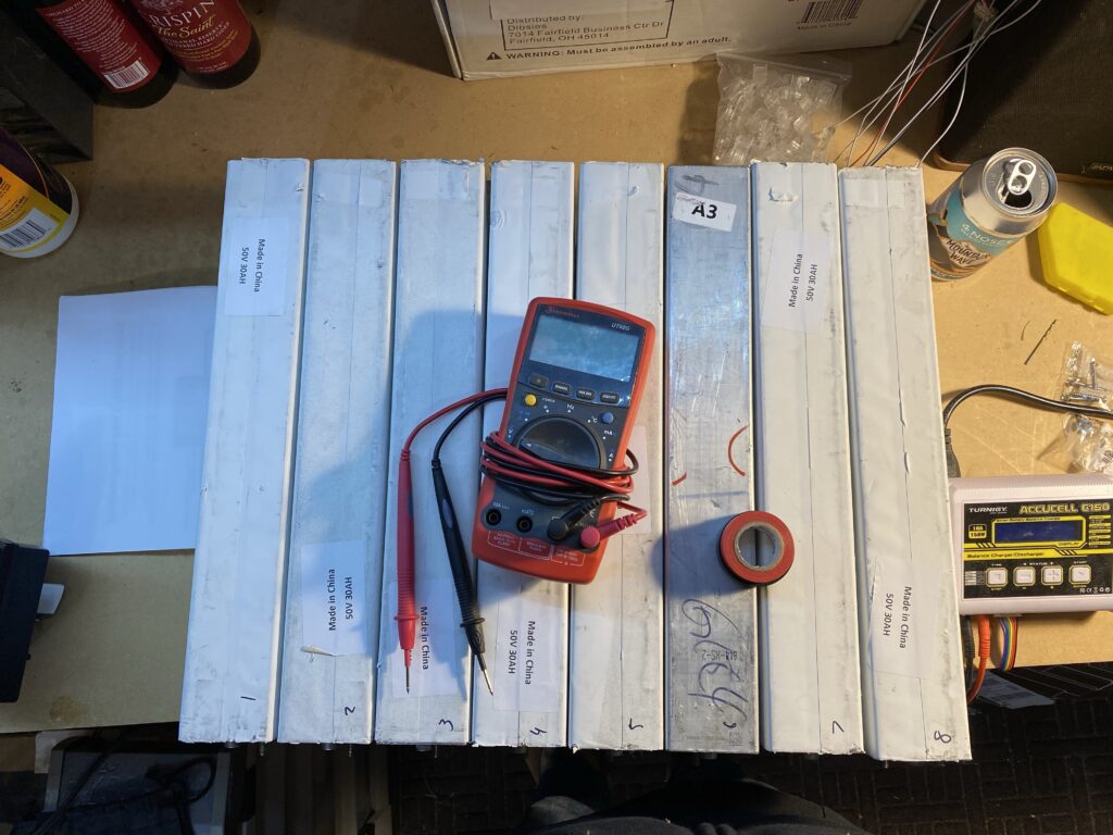
Upon unboxing, I made sure to record the resting voltage of each cell. Below were the resting voltages:
| cell | voltage |
| 1 | 3.341 |
| 2 | 3.345 |
| 3 | 3.435 |
| 4 | 3.339 |
| 5 | 3.351 |
| 6 | 3.376 |
| 7 | 3.343 |
| 8 | 3.363 |
| min | 3.339 |
| max | 3.435 |
| avg | 3.362 |
| delta | 0.096 |
Cell #2 had the lowest voltage and cell #3 the highest. This presented an easy chance to test out my bus bars for voltage equalization. I did not measure the cell internal resistance so I wasn’t really sure how much current would flow from cell 3 to 2 when shorted together so I did a quick estimate based on Ohm’s law (V=IR -> I=V/R). With an estimated internal resistance (IR) of 20 milliohms (I’ve had LiPo in this range after some degradation), and a voltage difference of 0.096V, that would mean a current of 0.096/0.020=4.8A. That wasn’t a huge number so I was comforable just connecting the cells with the bus bars. But first I wanted to actually measure with a multimeter.
I was expecting about 5A based on the calculation above. I’m not sure how I was 10x off on the estimate but after hooking up my multimeter, the equalization current was 0.6A. That was plenty low so I set my mind to balancing. But before that, I needed bus bars to connect all the cells in parallel.
Constructing copper bus bars
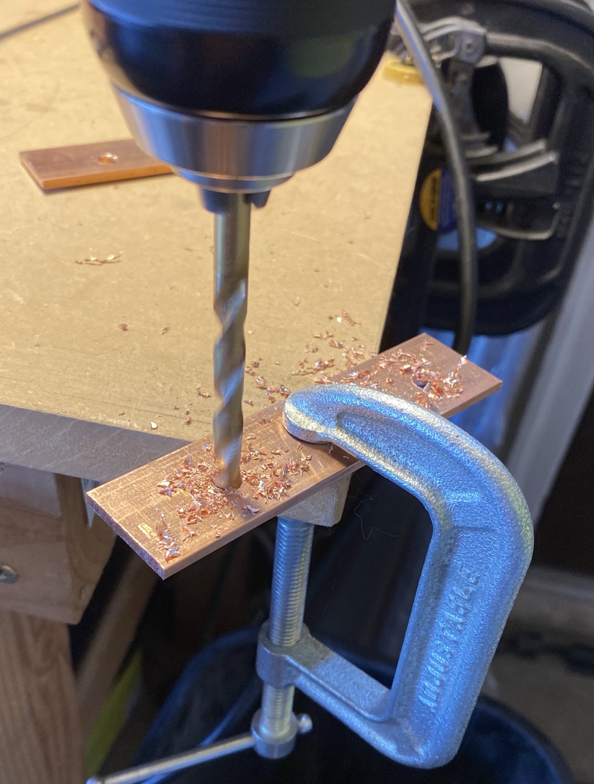
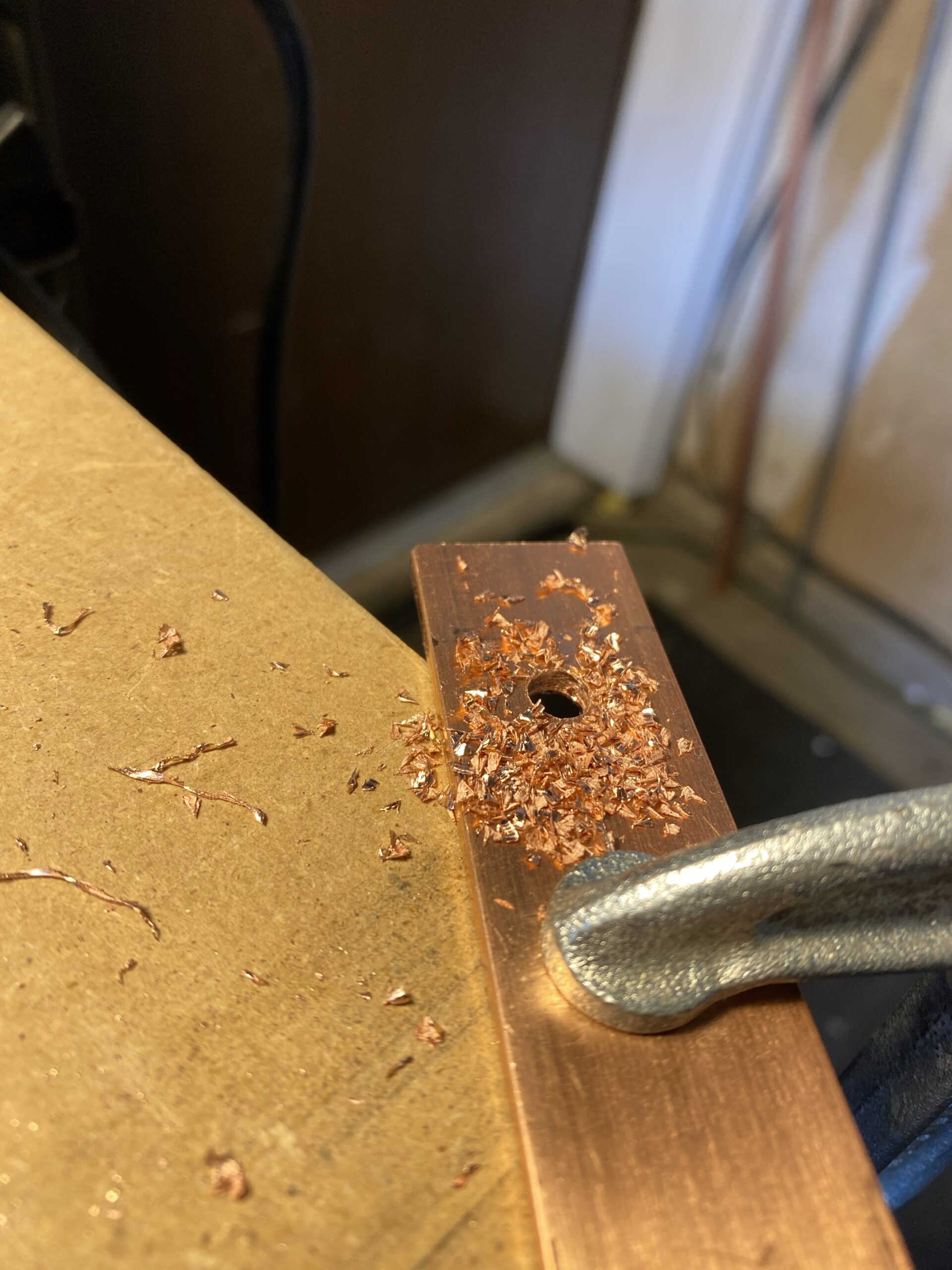
Bus bars are used to conduct high amounts of current in electrical applications. In essence, they are oversized, flat wires. I ordered 2x copper bars from McMaster Carr that are 1″x1/8″x3′. They arrived in two days with free shipping… Amazon is gaining competition. I got to work drilling holes.


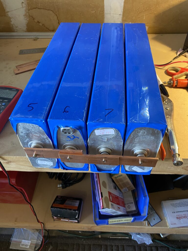
Heat shrinking the cells
With the bus bars ready, it was time to heat shrink the battery cells. Battery Hookup said they were uncovered and needed to be heat shrunk for every cell. Turns out 7 of 8 had a covering on them already. I heat shrunk them anyways for two reasons: 1) to further protect the cells from damage and short circuits and 2) so they look better. The cell on the left will be re-done with more heat shrink. I guestimated how much I needed and was short a few inches.

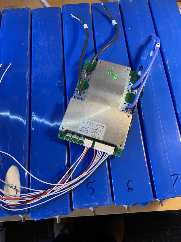
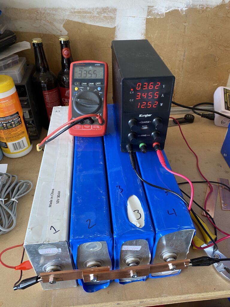
Balancing in 2 sets of 4 cells each
When making the bus bars, I put together a mental picture of what I needed to make and how many I needed. This worked fine for the final battery but I would need double for balancing. I had the full extra 3′ copper bar but it took forever to cut so I just decided to balance the cells in 2 groups of 4. Balancing is charging all cells in parallel as one low voltage, giant capacity battery to their rated voltage (3.65V for LiFePO4). Doing 4 cells at a time meant it was a 3.2V battery with a capacity of 1040 amp hours. The resting voltages were in the upper end of the voltage curve chart so it wouldn’t take super long. If the battery was fully depleted, it would take 104 hours at the 10 amps my bench power supply puts out.
So I got the bus bars hooked up and started balancing by setting my power supply to 3.65V and current to max.
Measurement discrepancies and voltage drop
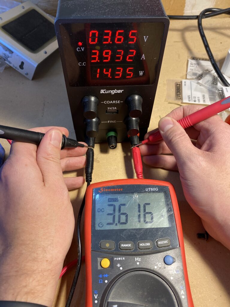
The first thing I did when I started charging was take voltage measurements to make sure things were right. I noticed some irregularities.
The first irregularity was the fact that the bench power supply was over-reporting the voltage by 0.034V or so when comparing the display to the terminals. This isn’t a huge deal and is actually a pretty decent level of accuracy for a $40 bench power supply from Amazon.
The next thing I noticed is that for a 10A power supply, it is putting out a lot less than 10A. So I measured the voltage at the bus bars.
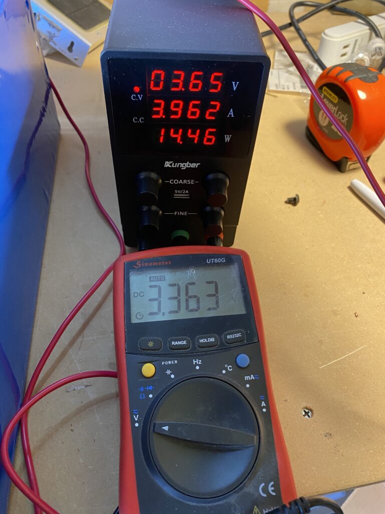
By leaving the voltage set to 3.65V at the DC power supply, the voltage drop means I wouldn’t get anywhere the rated 10A. The actual drop would decrease proportionally as the battery voltage neared the terminal voltage.
Regardless, it only took a couple hours until the cells were topped off for each set of 4. They are currently resting. I will check their voltages again tomorrow morning. The amount the cells drop in voltage from where they left off indicates the strength of the cell, with larger drops meaning weaker cells.
Conclusion
This is where we will leave off for the day. The 8 cells have been balanced in 2 groups of 4 and are currently resting. After 24 hours I will recheck the voltages to see which cells are strong and which are weak. I need to buy more electrical tape to cover up the bus bar ends (I did start assembling the full battery but stopped because the potential for short-circuit was higher than I was comfortable with).
As of 5/17/2021, things are up and running! Check it out at DIY solar with battery backup – up and running!
Disclosure: When you click on links to various merchants in this post and make a purchase, this can result in this site earning a commission. Affiliate programs and affiliations include, but are not limited to, the eBay Partner Network.