Introduction
Lots of acronyms in that title. If I expand them out, it says – “microsecond accurate network time protocol with a Raspberry Pi and pulse per second global positioning system [receiver]”. What it means is you can get super accurate timekeeping (1 microsecond = 0.000001 seconds) with a Raspberry Pi and a GPS receiver (the GT-U7 is less than $12) that spits out pulses every second. By following this guide, you will your very own Stratum 1 NTP server at home!
2025 Update – I wrote a new post with some newer best practices and guidance for 2025, including how to synchronize machines with nanosecond precision using PTP (precision time protocol). Read that post first then come back here – not all discussion is in both places.
Why would you need time this accurate at home?
You don’t. There aren’t many applications for this level of timekeeping in general, and even fewer at home. But this blog is called Austin’s Nerdy Things so here we are. Using standard, default internet NTP these days will get your computers to within a 10-20 milliseconds of actual time (1 millisecond = 0.001 seconds). By default, Windows computers get time from time.windows.com. MacOS computers get time from time.apple.com. Linux devices get time from [entity].pool.ntp.org, like debian.pool.ntp.org. PPS gets you to the next SI prefix in terms of accuracy (milli -> micro), which means 1000x more accurate timekeeping.
YouTube video link
If you prefer a video version – https://www.youtube.com/watch?v=YfgX7qPeiqQ
Materials needed
- Raspberry Pi (either the 3 or the 4 will work)
- GPS with PPS output – Adafruit Ultimate GPS ($40ish) or the GT-U7 ($12ish)
- (optional) – a GPS antenna (for getting better GPS satellite reception)
- Wires to connect it all up (5 wires needed – 5V/RX/TX/GND/PPS)
- 15-30 minutes
Steps
0 – Update your Pi and install packages
This NTP guide assumes you have a Raspberry Pi ready to go. If you don’t, I have a 16 minute video on YouTube that goes through flashing the SD card and initial setup – https://youtu.be/u5dHvEYwr9M.
You should update your Pi to latest before basically any project. We will install some other packages as well. pps-tools help us check that the Pi is receiving PPS signals from the GPS module. We also need GPSd for the GPS decoding of both time and position. I use chrony instead of NTPd because it seems to sync faster than NTPd in most instances and also handles PPS without compiling from source (the default Raspbian NTP doesn’t do PPS) Installing chrony will remove ntpd.
sudo apt update
sudo apt upgrade
sudo rpi-update
sudo apt install pps-tools gpsd gpsd-clients python-gps chrony
1 – add GPIO and module info where needed
In /boot/config.txt, add ‘dtoverlay=pps-gpio,gpiopin=18’ to a new line. This is necessary for PPS. If you want to get the NMEA data from the serial line, you must also enable UART and set the initial baud rate.
sudo bash -c "echo '# the next 3 lines are for GPS PPS signals' >> /boot/config.txt"
sudo bash -c "echo 'dtoverlay=pps-gpio,gpiopin=18' >> /boot/config.txt"
sudo bash -c "echo 'enable_uart=1' >> /boot/config.txt"
sudo bash -c "echo 'init_uart_baud=9600' >> /boot/config.txt"
In /etc/modules, add ‘pps-gpio’ to a new line.
sudo bash -c "echo 'pps-gpio' >> /etc/modules"
Reboot
sudo reboot
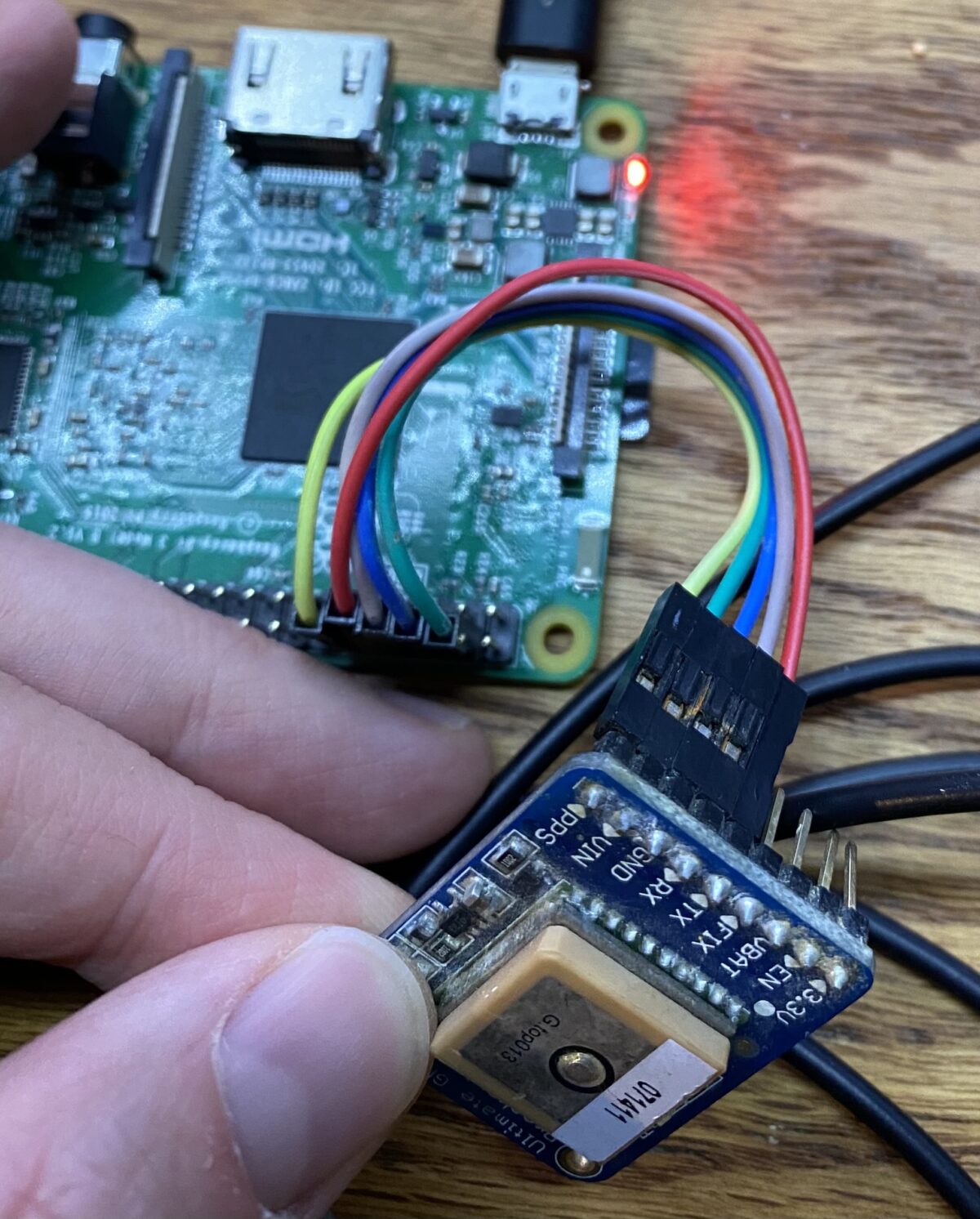
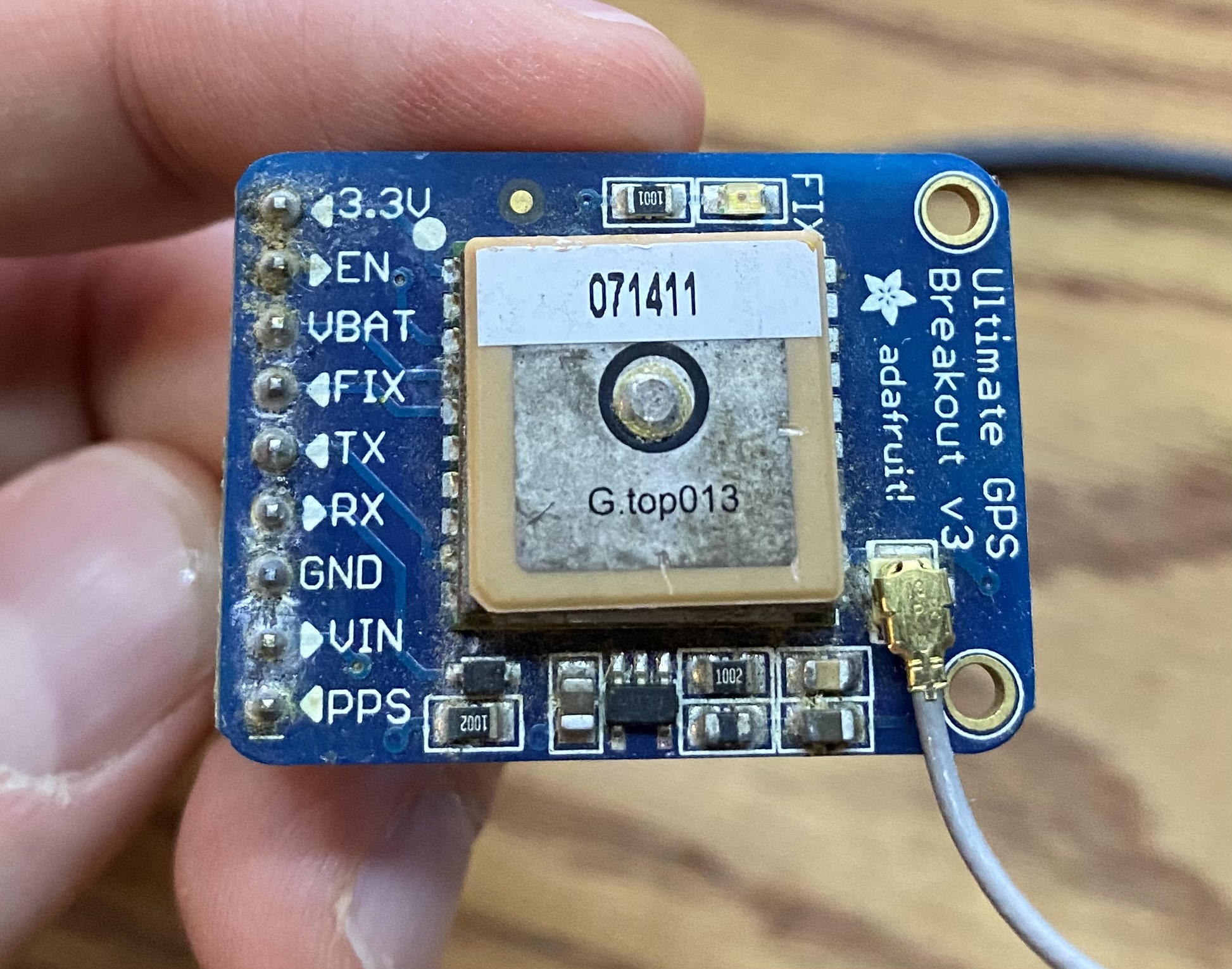
2 – wire up the GPS module to the Pi
I used the Adafruit Ultimate GPS breakout. It has 9 pins but we are only interested in 5. There is also the Adafruit GPS hat which fits right on the Pi but that seems expensive for what it does (but it is significantly neater in terms of wiring).
Pin connections:
- GPS PPS to RPi pin 12 (GPIO 18)
- GPS VIN to RPi pin 2 or 4
- GPS GND to RPi pin 6
- GPS RX to RPi pin 8
- GPS TX to RPi pin 10
- see 2nd picture for a visual

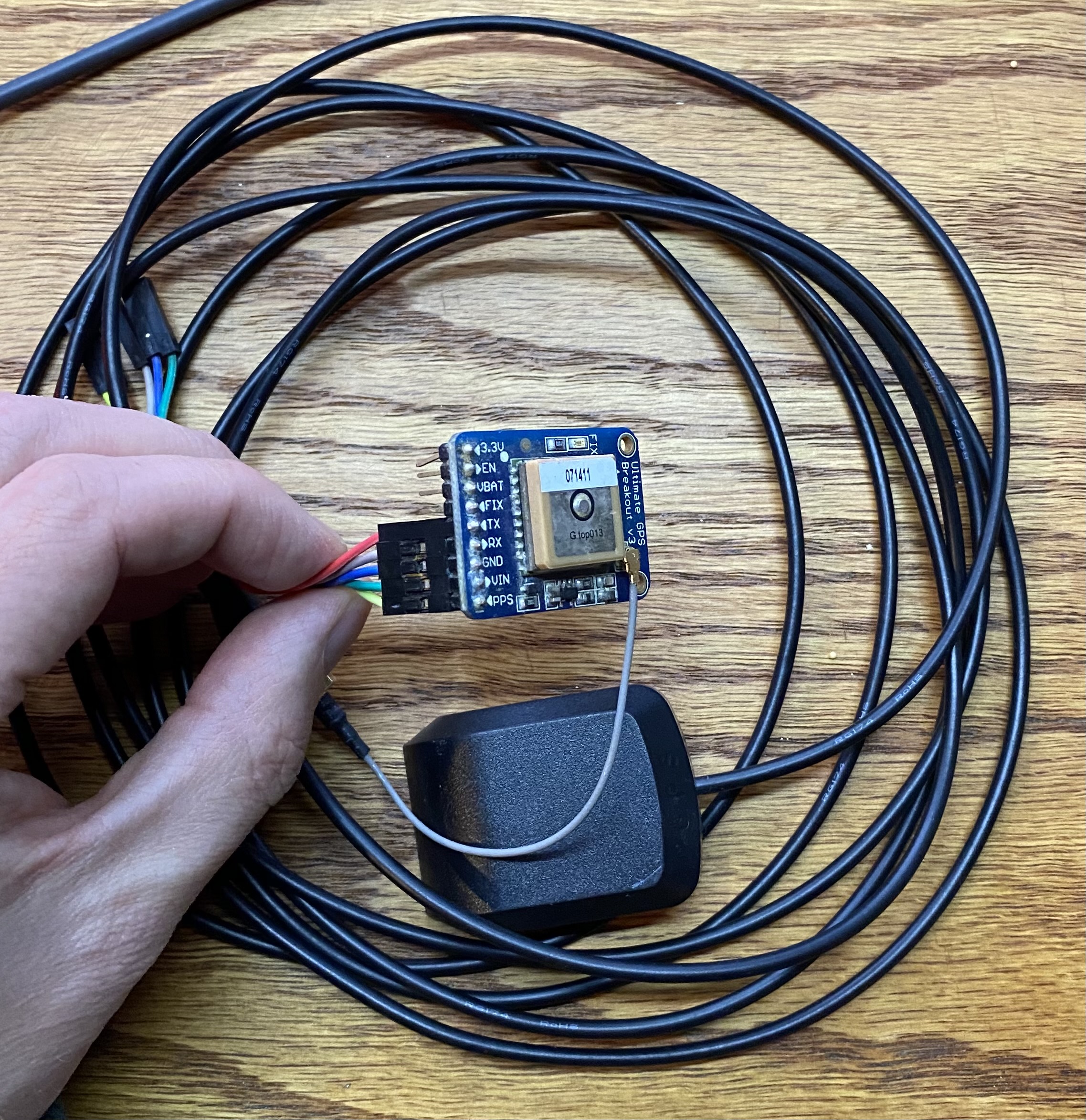
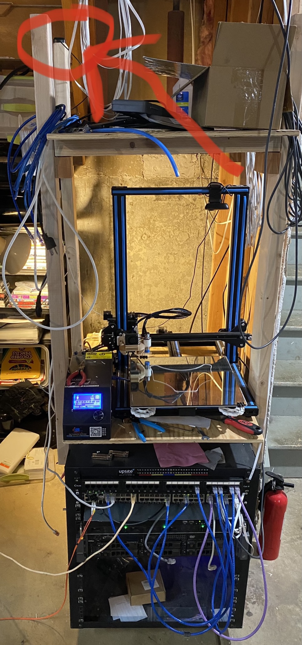
Now place your GPS antenna (if you have one) in a spot with a good view of the sky. If you don’t have an antenna, you might have to get a bit creative with how you locate your Raspberry Pi with attached GPS.
I honestly have my antenna in the basement (with only the kitchen and attic above) and I generally have 8-10 satellites locked all the time (11 as of writing). Guess that means the antenna works better than expected! Either way, better exposure to the sky will in theory work better. Pic:
2.5 – free up the UART serial port for the GPS device
Run raspi-config -> 3 – Interface options -> I6 – Serial Port -> Would you like a login shell to be available over serial -> No. -> Would you like the serial port hardware to be enabled -> Yes.
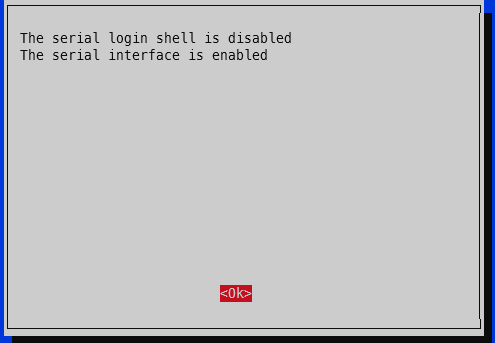
Finish. Yes to reboot.
3 – check that PPS is working
First, check that the PPS module is loaded:
lsmod | grep pps
The output should be like:
pi@raspberrypi:~ $ lsmod | grep pps
pps_gpio               16384  0
pps_core               16384  1 pps_gpio
Second, check for the PPS pulses:
sudo ppstest /dev/pps0
The output should spit out a new line every second that looks something like this (your output will be a bit farther from x.000000 since it isn’t yet using the GPS PPS):
pi@pi-ntp:~ $ sudo ppstest /dev/pps0
trying PPS source "/dev/pps0"
found PPS source "/dev/pps0"
ok, found 1 source(s), now start fetching data...
source 0 - assert 1618799061.999999504, sequence: 882184 - clear  0.000000000, sequence: 0
source 0 - assert 1618799062.999999305, sequence: 882185 - clear  0.000000000, sequence: 0
source 0 - assert 1618799063.999997231, sequence: 882186 - clear  0.000000000, sequence: 0
source 0 - assert 1618799064.999996827, sequence: 882187 - clear  0.000000000, sequence: 0
source 0 - assert 1618799065.999995852, sequence: 882188 - clear  0.000000000, sequence: 0
^C
4 – change GPSd to start immediately upon boot
Edit /etc/default/gpsd and change GPSD_OPTIONS=”” to GPSD_OPTIONS=”-n” and change DEVICES=”” to DEVICES=”/dev/ttyS0 /dev/pps0″, then reboot. My full /etc/default/gpsd is below:
pi@raspberrypi:~ $ sudo cat /etc/default/gpsd
# Default settings for the gpsd init script and the hotplug wrapper.

# Start the gpsd daemon automatically at boot time
START_DAEMON="true"

# Use USB hotplugging to add new USB devices automatically to the daemon
USBAUTO="true"

# Devices gpsd should collect to at boot time.
# They need to be read/writeable, either by user gpsd or the group dialout.
DEVICES="/dev/ttyS0 /dev/pps0"

# Other options you want to pass to gpsd
GPSD_OPTIONS="-n"
sudo reboot
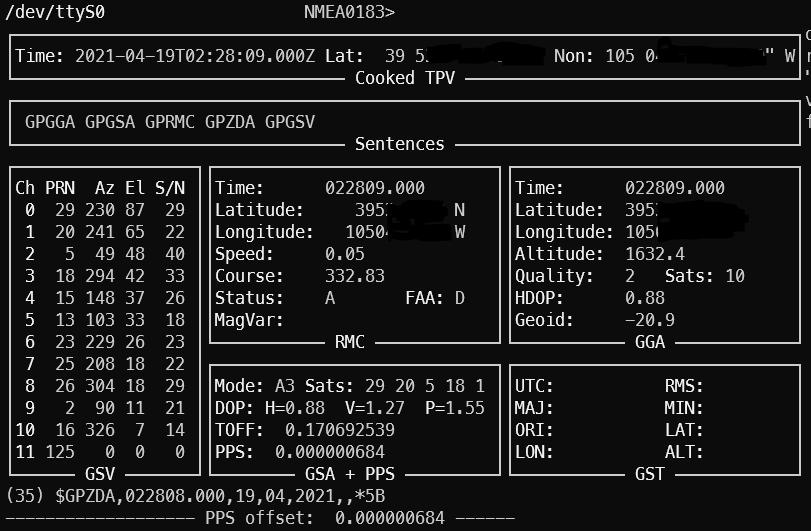
4.5 – check GPS for good measure
To ensure your GPS has a valid position, you can run gpsmon or cgps to check satellites and such. This check also ensures GPSd is functioning as expected. If your GPS doesn’t have a position solution, you won’t get a good time signal. If GPSd isn’t working, you won’t get any updates on the screen. The top portion will show the analyzed GPS data and the bottom portion will scroll by with the raw GPS sentences from the GPS module.
5 – edit config files
For chrony, add these two lines to the /etc/chrony/chrony.conf file somewhere near the rest of the server lines:
refclock SHM 0 refid NMEA offset 0.200
refclock PPS /dev/pps0 refid PPS lock NMEA
2025 update: see the newer post chrony config for how to get single source (i.e. just your single GPS to use both NMEA and PPS) timing to works successfully.
My entire /etc/chrony/chrony.conf file looks like this:
###### below this line are custom config changes #######
server 10.98.1.1 iburst minpoll 3 maxpoll 5
server time-a-b.nist.gov iburst
server time-d-b.nist.gov
server utcnist.colorado.edu
server time.windows.com
server time.apple.com

# delay determined experimentally by setting noselect then monitoring for a few hours
# 0.325 means the NMEA time sentence arrives 325 milliseconds after the PPS pulse
# the delay adjusts it forward
refclock SHM 0 delay 0.325 refid NMEA
refclock PPS /dev/pps0 refid PPS

allow 10.98.1.0/24 # my home network
###### above this line are custom config changes #######

###### below this line is standard chrony stuff #######
keyfile /etc/chrony/chrony.keys
driftfile /var/lib/chrony/chrony.drift
#log tracking measurements statistics
logdir /var/log/chrony
maxupdateskew 100.0
hwclockfile /etc/adjtime
rtcsync
makestep 1 3
Restart chrony, wait a few minutes, and verify.
sudo systemctl restart chrony
5 – verify the NTP server is using the GPS PPS
Right after a chrony restart, the sources will look like this (shown by running ‘chronyc sources’)
pi@pi-ntp:~ $ chronyc sources
210 Number of sources = 9
MS Name/IP address         Stratum Poll Reach LastRx Last sample
===============================================================================
#? NMEA                          0   4     0     -     +0ns[   +0ns] +/-    0ns
#? PPS                           0   4     0     -     +0ns[   +0ns] +/-    0ns
^? pfsense.home.fluffnet.net     0   3     3     -     +0ns[   +0ns] +/-    0ns
^? time-a-b.nist.gov             1   6     3     1  -2615us[-2615us] +/- 8218us
^? time-d-b.nist.gov             1   6     1     3  -2495us[-2495us] +/- 7943us
^? india.colorado.edu            0   6     0     -     +0ns[   +0ns] +/-    0ns
^? 13.86.101.172                 3   6     1     4  -4866us[-4866us] +/-   43ms
^? usdal4-ntp-002.aaplimg.c>     1   6     1     4  -2143us[-2143us] +/-   13ms
^? time.cloudflare.com           3   6     1     3  -3747us[-3747us] +/- 9088us
The # means locally connected source of time. The question marks mean it is still determine the status of each source.
After a couple minutes, you can check again:
pi@pi-ntp:~ $ chronyc -n sources
210 Number of sources = 9
MS Name/IP address         Stratum Poll Reach LastRx Last sample
===============================================================================
#x NMEA                          0   4   377    23    -37ms[  -37ms] +/- 1638us
#* PPS                           0   4   377    25   -175ns[ -289ns] +/-  126ns
^? 10.98.1.1                     0   5   377     -     +0ns[   +0ns] +/-    0ns
^- 132.163.96.1                  1   6   177    22  -3046us[-3046us] +/- 8233us
^- 2610:20:6f96:96::4            1   6    17    28  -2524us[-2524us] +/- 7677us
^? 128.138.140.44                1   6     3    30  -3107us[-3107us] +/- 8460us
^- 13.86.101.172                 3   6    17    28  -8233us[-8233us] +/-   47ms
^- 17.253.2.253                  1   6    17    29  -3048us[-3048us] +/-   14ms
^- 2606:4700:f1::123             3   6    17    29  -3325us[-3325us] +/- 8488us
For the S column, * means the source that is active. + means it is considered a good source and would be used if the current one is determined to be bad or is unavailable. The x shown for the NMEA source means it is a “false ticker”, which means it isn’t being used. In our case that is fine because the PPS source is active and valid. Anything else generally means it won’t be used.
In this case, chrony is using the PPS signal. The value inside the brackets is how far off chrony is from the source. It is showing that we are 289 nanoseconds off of GPS PPS time. This is very, very close to atomic clock level accuracy. The last column (after the +/-) includes latency to the NTP source as well as how far out of sync chrony thinks it is (for example, the 17.253.2.253 server is 12.5 milliseconds away one-way via ping):
pi@pi-ntp:~ $ ping -c 5 17.253.2.253
PING 17.253.2.253 (17.253.2.253) 56(84) bytes of data.
64 bytes from 17.253.2.253: icmp_seq=1 ttl=54 time=25.2 ms
64 bytes from 17.253.2.253: icmp_seq=2 ttl=54 time=27.7 ms
64 bytes from 17.253.2.253: icmp_seq=3 ttl=54 time=23.8 ms
64 bytes from 17.253.2.253: icmp_seq=4 ttl=54 time=24.4 ms
64 bytes from 17.253.2.253: icmp_seq=5 ttl=54 time=23.4 ms

--- 17.253.2.253 ping statistics ---
5 packets transmitted, 5 received, 0% packet loss, time 4007ms
rtt min/avg/max/mdev = 23.403/24.954/27.780/1.547 ms
For a full list of information about how to interpret these results, check here – https://docs.fedoraproject.org/en-US/Fedora/18/html/System_Administrators_Guide/sect-Checking_if_chrony_is_synchronized.html
6 – results
A day after the bulk of writing this post, I turned on logging via the .conf file and restarted chrony. It settled to microsecond level accuracy in 57 seconds. For the offset column, the scientific notation e-7 means the results are in nanoseconds. This means that for the 19:54:35 line, the clock is -450.9 nanoseconds off of the PPS signal. There is that e-10 line in there which says that it is 831 picoseconds off PPS (I had to look up SI prefixes to make sure pico came after nano! also I doubt the Pi can actually keep track of time that closely.). After the initial sync, there is only 1 line in the below log that is actually at the microsecond level (the others are all better than microsecond) – the 20:00:59 entry, which shows the clock is -1.183 microseconds off.
Things that affect timekeeping on the Pi
Thought I’d toss in this section for completeness (i.e. thanks for all the good info Austin but how can I make this even better?). There are a few things that affect how well the time is kept on the Pi:
- Ambient temperature around the Pi – if you plot the freq PPM against ambient temperature, there will be a clear trend. The more stable the ambient temp, the less variation in timekeeping.
- Load on the Pi – similar to above. Highly variable loads will make the processor work harder and easier. Harder working processor means more heat. More heat means more variability. These crystals are physical devices after all.
- GPS reception – they actually making timing GPS chips that prefer satellites directly overhead. They have better ability to filter out multipathing and such. In general, the better the GPS reception, the better the PPS signal.
Conclusion
After running through the steps in this guide, you should now have a functional Stratum 1 NTP server running on your Raspberry Pi with microsecond level accuracy provided by a PPS GPS. This system can obtain time in the absence of any external sources other than the GPS (for example, internet time servers), and then sync up with the extremely precise GPS PPS signal. Our NTP GPS PPS clock is now within a few microseconds of actual GPS time.
Update 2024-01-19: RIP Dave Mills, inventor/creator of NTP – https://arstechnica.com/gadgets/2024/01/inventor-of-ntp-protocol-that-keeps-time-on-billions-of-devices-dies-at-age-85/
Update 2025-11-25: See here for how to do some thermal management to improve the stability by a factor of at least 2x: https://austinsnerdythings.com/2025/11/24/worlds-most-stable-raspberry-pi-81-better-ntp-with-thermal-management/
References
I read a ton on https://www.satsignal.eu/ntp/Raspberry-Pi-NTP.html and other pages on that domain over the years which has been extremely helpful in getting GPS PPS NTP going for my setup. There is a lot of background info for how/why this stuff works and many useful graphics. Another source is https://wellnowweknow.com/index.php/2019/12/27/how-to-ntp-a-raspberry-pi-4-via-gps-and-pps/ for a short and sweet (maybe too short) set of commands.
Disclosure: When you click on links to various merchants in this post and make a purchase, this can result in this site earning a commission. Affiliate programs and affiliations include, but are not limited to, the eBay Partner Network.