Just getting this up as a draft now for a Reddit user.
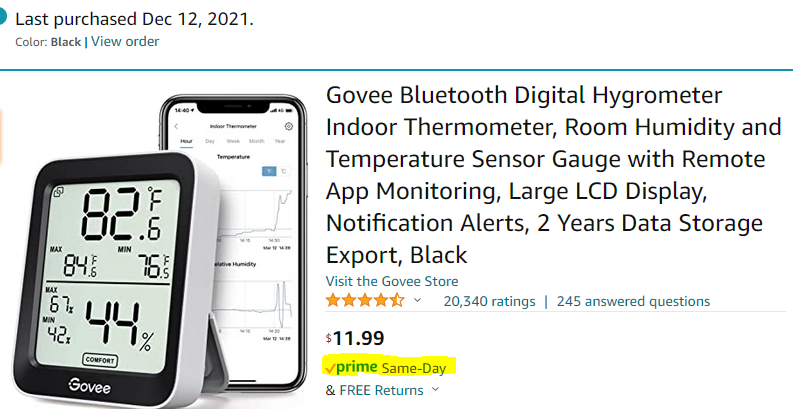
In short, this Python script reads the temperatures of two different sensors (outside from an The Ambient Weather WS-2902C weather station and in our master bedroom with a Govee Bluetooth Thermometer), the temperature set point for a generic thermostat entity, does some logic, and turns a switch on or off, all with the Home Assistant API. The switch control two basic box fans that are set to blow air into our bedroom from outside. It runs every X minutes (currently set to 5). This method works great if nighttime temperatures drop below 70F before bedtime. We like the bedroom temp at 66F, so unless it gets below 70F by around 9PM, it probably won’t cool enough for us to be comfortable enough to fall asleep. My wife wakes up at 5:45am, me at 6:30am, pending what our 22 month old daughter thinks of that schedule, so we typically aim to be asleep by 10pm.
Today, 2022-05-14, was the day I got out the window AC. It will be in place for the rest of the summer.
Requirements:
- A working Home Assistant installation (mine is Python venv install in a Ubuntu VM)
- A bearer token authorization code for a/your Home Assistant user
- A working MQTT installation
- A switch controllable by Home Assistant
- 1-2 box fans plugged into said switch controlled by Home Assistant
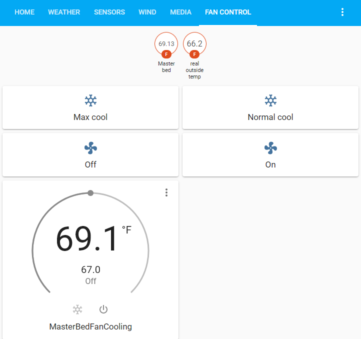
Here is what the Home Assistant control screen looks like. The buttons should be self explanatory. The generic thermostat entity doesn’t need to be on/active for this to work. It uses the set point for control purposes (set to 67.0F in the screenshot).
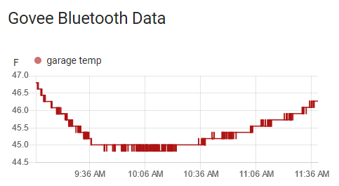
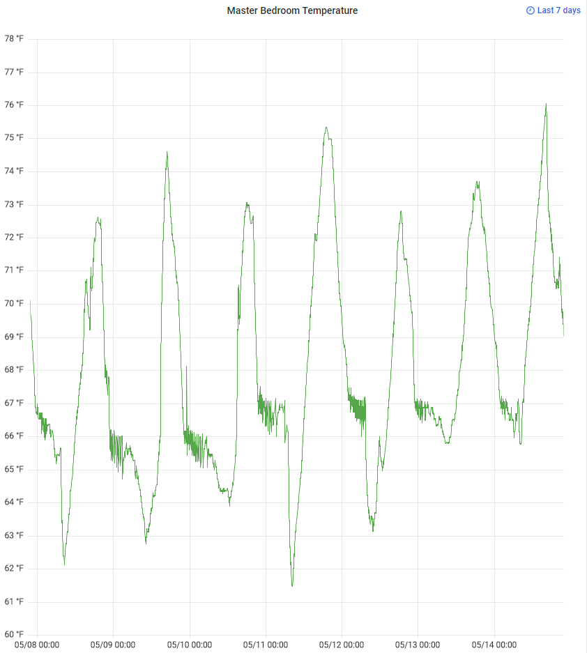
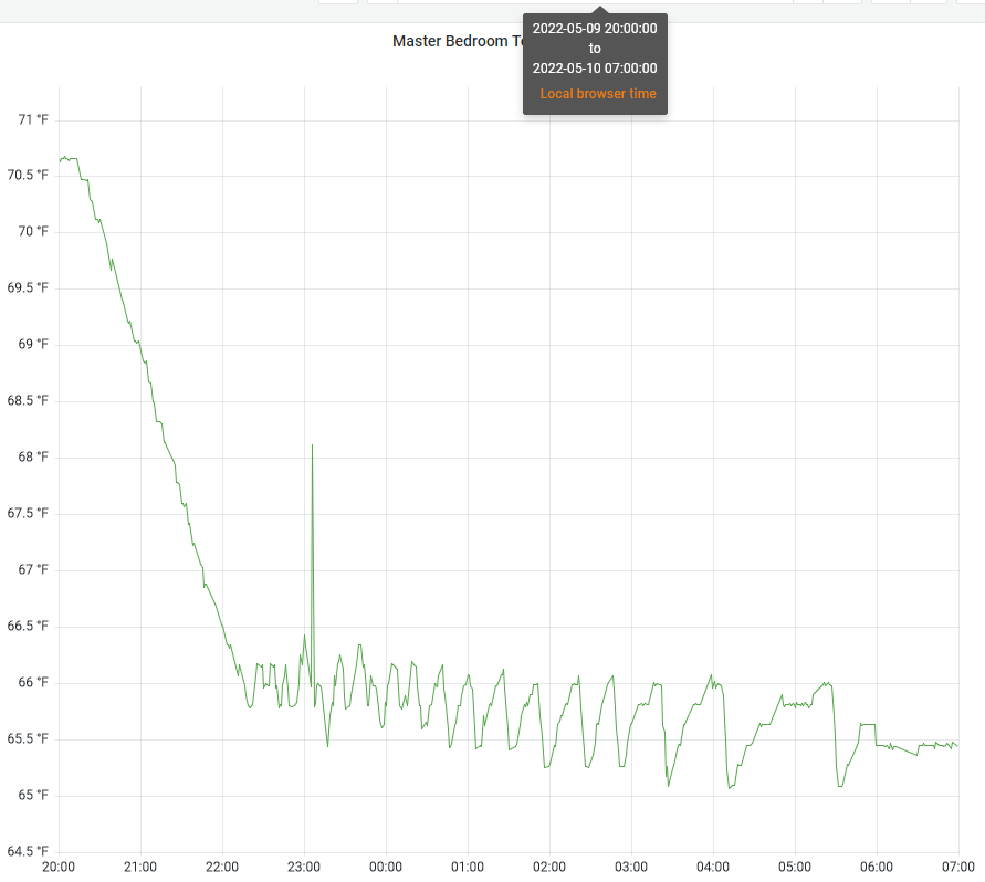
I believe there is currently a logic bug with max cool not respecting the delta_temp variable. Other than that it works perfect. Below is a screenshot of the last 7 days showing the room cooling off nicely to the setpoint of 66F on nights 1-3 and 67F on nights 4-7. Switching a control device on and off every so often is a version of a bang-bang controller. If you look closely, you will notice that each cycle on and off results in a greater temperature drop, which is due to the colder outside air being blown in for the same duration regardless of delta T.
import json
import datetime
import time
from dateutil import parser
from requests import get, post
import paho.mqtt.client as mqttClient
import logging

logging.basicConfig(
    format='%(asctime)s - %(name)s - %(levelname)s - %(message)s', level=logging.DEBUG)

loggers_to_set_to_warning = ['urllib3.connectionpool']
for l in loggers_to_set_to_warning:
    logging.getLogger(l).setLevel(logging.WARNING)

delta_temp = 3.0
mqtt_host = "mqtt.example.com"
mqtt_port = 1883

base_url = "http://ha.example.come:8123/"
states_url = base_url + "api/states/"
switch_url = base_url + "api/services/switch"
bearer_token = "ey...Vw"
full_bearer_token = "Bearer " + bearer_token
request_headers = {
    "Authorization": full_bearer_token,
    "content-type": "application/json"
}
endpoints = ["climate.masterbedfancooling",
             "sensor.real_outside_temp"]
fan_switch_entity_id = "switch.fan_switch"
states = {}
climate_topic = "climate/fan_control_state"
current_state = "off"
last_state = None
desired_seconds_to_sleep = 300
max_cool_outdoor_temp_limit = 66
desired_temp = None
outside_temp = None
current_temp = None
next_fan_action_time = datetime.datetime.now()


def set_fan_switch_state(state):
    new_fan_state = None
    if state == "on":
        new_fan_state = "on"
    elif state == "off":
        new_fan_state = "off"
    else:
        logging.warn("requested fan state unknown")
        return

    entity_info = {"entity_id": fan_switch_entity_id}
    full_url = switch_url + "/turn_" + new_fan_state
    response = post(full_url, headers=request_headers,
                    data=json.dumps(entity_info))
    if response.status_code != 200:
        logging.error(
            f"attempted to set fan state to {new_fan_state} but encountered error with status code: {response.status_code}")
    else:
        logging.info(f"successfully set fan state to {new_fan_state}")


def set_state_from_mqtt_message(message):
    global current_state, next_fan_action_time
    if message == "max_cool":
        current_state = "max_cool"
    elif message == "normal_cool":
        current_state = "normal_cool"
    elif message == "off":
        current_state = "off"
    elif message == "on":
        current_state = "on"
    else:
        logging.error(f"unable to determine state, setting to off")
        current_state = "off"
    logging.info(f"current_state set to: {current_state}")
    next_fan_action_time = datetime.datetime.now()


def connect_mqtt():
    # Set Connecting Client ID
    client = mqttClient.Client("python_window_fan_control")
    #client.username_pw_set(username, password)
    client.on_connect = on_connect
    client.connect(mqtt_host, mqtt_port)
    return client


def on_connect(client, userdata, flags, rc):
    if rc == 0:
        logging.info("Connected to MQTT Broker!")
    else:
        logging.info("Failed to connect, return code %d\n", rc)


def on_message(client, userdata, msg):
    logging.info(f"Received `{msg.payload.decode()}` from `{msg.topic}` topic")
    set_state_from_mqtt_message(msg.payload.decode())


def on_subscribe(client, userdata, mid, granted_qos):
    logging.info(f"subscribed to topic")


def set_fan_state(state):
    if state == "on":
        logging.info(f"setting fan state to on")
        set_fan_switch_state("on")
    elif state == "off":
        logging.info(f"setting fan state to off")
        set_fan_switch_state("off")


def get_and_set_temperatures():
    global desired_temp, current_temp, outside_temp
    logging.debug("executing loop")

    for endpoint in endpoints:
        full_url = states_url + endpoint
        response = get(full_url, headers=request_headers)
        parsed_json = json.loads(response.text)
        entity = parsed_json['entity_id']
        hvac_action = ""
        if endpoint == 'climate.masterbedfancooling':
            desired_temp = float(
                parsed_json['attributes']['temperature'])
            current_temp = float(
                parsed_json['attributes']['current_temperature'])
            hvac_action = parsed_json['attributes']['hvac_action']
        elif endpoint == 'sensor.real_outside_temp':
            outside_temp = float(parsed_json['state'])
        last_updated = parser.parse(parsed_json['last_updated'])
    logging.info(
        f"temps: current={current_temp}, desired={desired_temp}, outside={outside_temp}")
    if desired_temp == None or current_temp == None or outside_temp == None:
        logging.error(
            "one or more temps invalid, turning off switch and breaking execution")
        set_fan_state("off")


client = mqttClient.Client("window-fan-client")
client.on_connect = on_connect
client.on_message = on_message
client.on_subscribe = on_subscribe
client.connect(mqtt_host, mqtt_port)
client.subscribe(climate_topic)
client.loop_start()

while(True):
    # logging.info("loop")
    if datetime.datetime.now() > next_fan_action_time:
        logging.info("fan action time")
        if current_state == "off":
            new_fan_state = "off"
            logging.info(
                f"current_state is {current_state}, turning fan {new_fan_state}")
            set_fan_state("off")
        else:
            get_and_set_temperatures()

        if current_state == "max_cool":
            logging.info(
                f"current_state is {current_state}, call for max cooling")
            if outside_temp < max_cool_outdoor_temp_limit:
                logging.info(
                    f"able to max_cool with outside temp: {outside_temp}, lower than {max_cool_outdoor_temp_limit} ")
                set_fan_state("on")
            elif outside_temp < (current_temp - delta_temp):
                logging.info(
                    f"unable to max cool, but still can cool with outside: {outside_temp} and inside: {current_temp}")
                set_fan_state("on")
            else:
                logging.info("unable to cool at all, turning fan off")
                set_fan_state("off")
        elif current_state == "normal_cool":
            logging.info(
                f"current_state is {current_state}")
            if (current_temp > desired_temp):
                logging.info(
                    f"call for cooling. current: {current_temp}, desired: {desired_temp}")
                if (current_temp > (outside_temp - delta_temp)):
                    logging.info("can cool, turning fan on")
                    set_fan_state("on")
                else:
                    logging.info("can't cool, turning fan off")
                    set_fan_state("off")
            else:
                logging.info("no need for cooling, turning fans off")
                set_fan_state("off")
        elif current_state == "on":
            new_fan_state = "on"
            logging.info(
                f"current_state is {current_state}, turning fan {new_fan_state}")
            set_fan_state("on")

        last_state = current_state
        next_fan_action_time = datetime.datetime.now() \
            + datetime.timedelta(seconds=desired_seconds_to_sleep)
        logging.info(f"next fan action in {desired_seconds_to_sleep} seconds")
        logging.info("---------loop end-------------------")
    else:
        #logging.debug("not fan action time yet, sleeping 1s")
        time.sleep(0.25)
    # actual_seconds_to_sleep = desired_seconds_to_sleep - datetime.datetime.now().minute % desired_seconds_to_sleep
    # seconds_to_sleep = actual_minutes_to_sleep * 60.0
    # logging.info(f"sleeping {desired_seconds_to_sleep}s")
    # time.sleep(desired_seconds_to_sleep)