After lecture 4
A lot of this stuff still isn’t making a ton of sense to me. I really struggled with how to init the theme for assignment 2. The key was optionals. How to do it came to me in the shower. I am writing this post after doing the changes from Lecture 4, Assignment 2, and Lecture 5 so I don’t have a whole lot specifically around lecture 4.
Code
The viewModel is now hooked up to both the View and the Model. This MVVM stuff is clicking for me, thankfully.
MemoryGame.swift – includes scoring:
//
//  MemoryGame.swift
//  Memorize
//
//  Created by Austin on 5/28/21.
//  austinsnerdythings.com

import Foundation

// model
struct MemoryGame<CardContent> where CardContent: Equatable {
    private(set) var cards: Array<Card>
    private var indexOfTheOneAndOnlyFaceUpCard: Int?
    private(set) var score = 0

    mutating func choose(_ card: Card) {
        if let chosenIndex = cards.firstIndex(where: { $0.id == card.id }),
           !cards[chosenIndex].isFaceUp,
           !cards[chosenIndex].isMatched
        {
            if let potentialMatchIndex = indexOfTheOneAndOnlyFaceUpCard {
                cards[chosenIndex].hasBeenSeenThisManyTimes += 1
                cards[potentialMatchIndex].hasBeenSeenThisManyTimes += 1
                if cards[chosenIndex].content == cards[potentialMatchIndex].content {
                    // match
                    cards[chosenIndex].isMatched = true
                    cards[potentialMatchIndex].isMatched = true
                    score += 2
                } else if cards[chosenIndex].hasBeenSeenThisManyTimes > 1 ||
							cards[potentialMatchIndex].hasBeenSeenThisManyTimes > 1 {
					// mismatch
					 score -= 1
				}
                indexOfTheOneAndOnlyFaceUpCard = nil
            } else {
                for index in cards.indices {
                    cards[index].isFaceUp = false
                }
                indexOfTheOneAndOnlyFaceUpCard = chosenIndex
            }

            cards[chosenIndex].isFaceUp.toggle()
        }
        print("\(cards)")
    }

    init(numberOfPairsOfCards: Int, createCardContent: (Int) -> CardContent) {
        cards = Array<Card>()
        // add number of pairs of cards x 2 cards to card array
        for pairIndex in 0..<numberOfPairsOfCards {
            let content: CardContent = createCardContent(pairIndex)
            cards.append(Card(content: content, id: pairIndex*2))
            cards.append(Card(content: content, id: pairIndex*2+1))

        }
        cards.shuffle()
    }

    struct Card: Identifiable {
        var isFaceUp: Bool = false
        var isMatched: Bool = false
        var content: CardContent
        var id: Int
        var hasBeenSeenThisManyTimes: Int = 0
    }
}
EmojiMemoryGame.swift – we’ve moved the theme stuff into its own struct/file
//
//  EmojiMemoryGame.swift
//  Memorize
//
//  Created by Austin on 5/28/21.
//  austinsnerdythings.com

import SwiftUI

// viewModel
class EmojiMemoryGame: ObservableObject {
    @Published private var gameModel: MemoryGame<String>
    private(set) var theme: Theme

    static func createMemoryGame(theme: Theme) -> MemoryGame<String> {
        let emojis: Array<String> = theme.emojis.shuffled()
		var cardsToShow = theme.numberOfPairsOfCards ?? Int.random(in: 3...theme.emojis.count)
		if cardsToShow > theme.emojis.count {
			cardsToShow = theme.emojis.count
		}
        return MemoryGame<String>(numberOfPairsOfCards: cardsToShow) { pairIndex in
            emojis[pairIndex]
        }
    }

	init(startingTheme: Theme? = nil)
    {
		let selectedTheme = startingTheme ?? themes.randomElement()!
		self.theme = selectedTheme
		gameModel = EmojiMemoryGame.createMemoryGame(theme: selectedTheme)
    }

    var cards: Array<MemoryGame<String>.Card> {
        return gameModel.cards
    }

	var score: Int {
		return gameModel.score
	}

    // MARK: - INTENTS
    func choose(_ card: MemoryGame<String>.Card) {
        gameModel.choose(card)
    }

    func startNewGame() {
        let newTheme = themes.randomElement()!
		self.theme = newTheme
		gameModel = EmojiMemoryGame.createMemoryGame(theme: newTheme)
    }
}
MemorizeApp.swift – added the viewModel argument to the init here
//
//  MemorizeApp.swift
//  Memorize
//
//  Created by Austin on 5/25/21.
//  austinsnerdythings.com

import SwiftUI

@main
struct MemorizeApp: App {
    let game = EmojiMemoryGame()

    var body: some Scene {
        WindowGroup {
            ContentView(viewModel: game)
        }
    }
}
Theme.swift
//
//  Theme.swift
//  Memorize
//
//  Created by Austin on 6/7/21.
//

import Foundation
import SwiftUI

//    struct Theme: Identifiable {
struct Theme {
    var name: String
    var emojis: [String]
    var numberOfPairsOfCards: Int?
    var baseColor: Color
}

let themes: [Theme] = [
	Theme(name: "vehicles",
		  emojis: ["?","?","?","?","?","?","?","?","?","?","?","?","?","✈️","?","?","?","?","?","?","?","?","?","?"],
		  baseColor: Color.red),
	Theme(name: "fruits",
		  emojis: ["?","?","?","?","?","?","?","?","?","?","?","?"],
		  baseColor: Color.yellow),
	Theme(name: "animals",
		  emojis: ["?","?","?","?","?","?","?","?","?","?","?","?"],
		  numberOfPairsOfCards: 20,
		  baseColor: Color.blue)

]
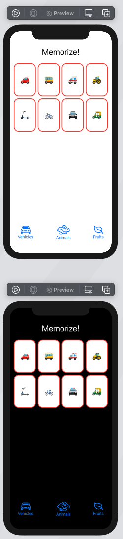
ContentView.swift
//
//  ContentView.swift
//  Memorize - Stanford CS193p, Spring 2021
//  After assignment 1
//
//  Created by Austin from austinsnerdythings.com on 5/27/21.
//

import SwiftUI

// view
struct ContentView: View {
    @ObservedObject var viewModel: EmojiMemoryGame

    var body: some View {
        VStack {
			HStack {
				Text("Memorize!").font(.largeTitle)
				Spacer()
				HStack {
					VStack {
						Text(viewModel.theme.name).font(.title)
						Text("Score: \(viewModel.score)")
					}
					Button("New Game") {
						viewModel.startNewGame()
					}
				}

			}
            ScrollView {
                LazyVGrid(columns: [GridItem(.adaptive(minimum: 80))]){
                    ForEach(viewModel.cards[0..<viewModel.cards.count]) { card in
                        CardView(card: card)
                            .aspectRatio(2/3, contentMode: .fit)
                            .onTapGesture {
                                viewModel.choose(card)
                            }
                    }
                }
            }
            .foregroundColor(viewModel.theme.baseColor)
            .font(.largeTitle)
            .padding(.horizontal)
        }
    }
}

struct CardView: View {
    let card: MemoryGame<String>.Card
    var body: some View {
        ZStack {
            let shape = RoundedRectangle(cornerRadius: 20)
            if card.isFaceUp {
                shape.fill().foregroundColor(.white)
                shape.strokeBorder(lineWidth: 3)
                Text(card.content).font(.largeTitle)
            } else if card.isMatched {
                shape.opacity(0)
            } else {
                shape.fill()
            }
        }

    }
}

struct ContentView_Previews: PreviewProvider {
    static var previews: some View {
        let game = EmojiMemoryGame()
        ContentView(viewModel: game)
            .preferredColorScheme(.light)
        ContentView(viewModel: game)
            .preferredColorScheme(.dark)
    }
}
References
I gained some inspiration (and cleared up a lot of confusion) from two GitHub repos:
- @pd95 – https://github.com/pd95/CS193p-Memorize/tree/main-2020-spring/Memorize
- @sk-ruban – https://github.com/sk-ruban/CS193p
Conclusion
Still a slog. Still learning. CS193p Spring 2021 Lecture 4 is probably where I would start wondering if I should drop the class if I was a Stanford student. The stuff from lecture 5 (post coming up) where Professor took 20 lines and shrunk it to 2 is still a bit much for me. He says it improves readability. It does, but stuffing everything into a single line does hinder debugging.