Introduction
Building off my last NTP post (Microsecond accurate NTP with a Raspberry Pi and PPS GPS), which required a $50-60 GPS device and a Raspberry Pi (also $40+), I have successfully tested something much cheaper, that is good enough, especially for initial PPS synchronization. Good enough, in this case, is defined as +/- 10 milliseconds, which can easily be achieved using a basic USB GPS device: GT-U7. Read on for instructions on how to set up the USB GPS as a Stratum 1 NTP time server.
YouTube Video Link
https://www.youtube.com/watch?v=DVtmDFpWkEs
Microsecond PPS time vs millisecond USB time
How accurate of time do you really need? The last post showed how to get all devices on a local area network (LAN) within 0.1 milliseconds of “real” time. Do you need you equipment to be that accurate to official atomic clock time (12:03:05.0001)? Didn’t think so. Do you care if every device is on the correct second compared to official/accurate time (12:03:05)? That’s a lot more reasonable. Using a u-blox USB GPS can get you to 0.01 seconds of official. The best part about this? The required USB GPS units are almost always less than $15 and you don’t need a Raspberry Pi.
Overview
This post will show how to add a u-blox USB GPS module to NTP as a driver or chrony (timekeeping daemon) as a reference clock (using GPSd shared memory for both) and verify the accuracy is within +/- 10 milliseconds.
Materials needed
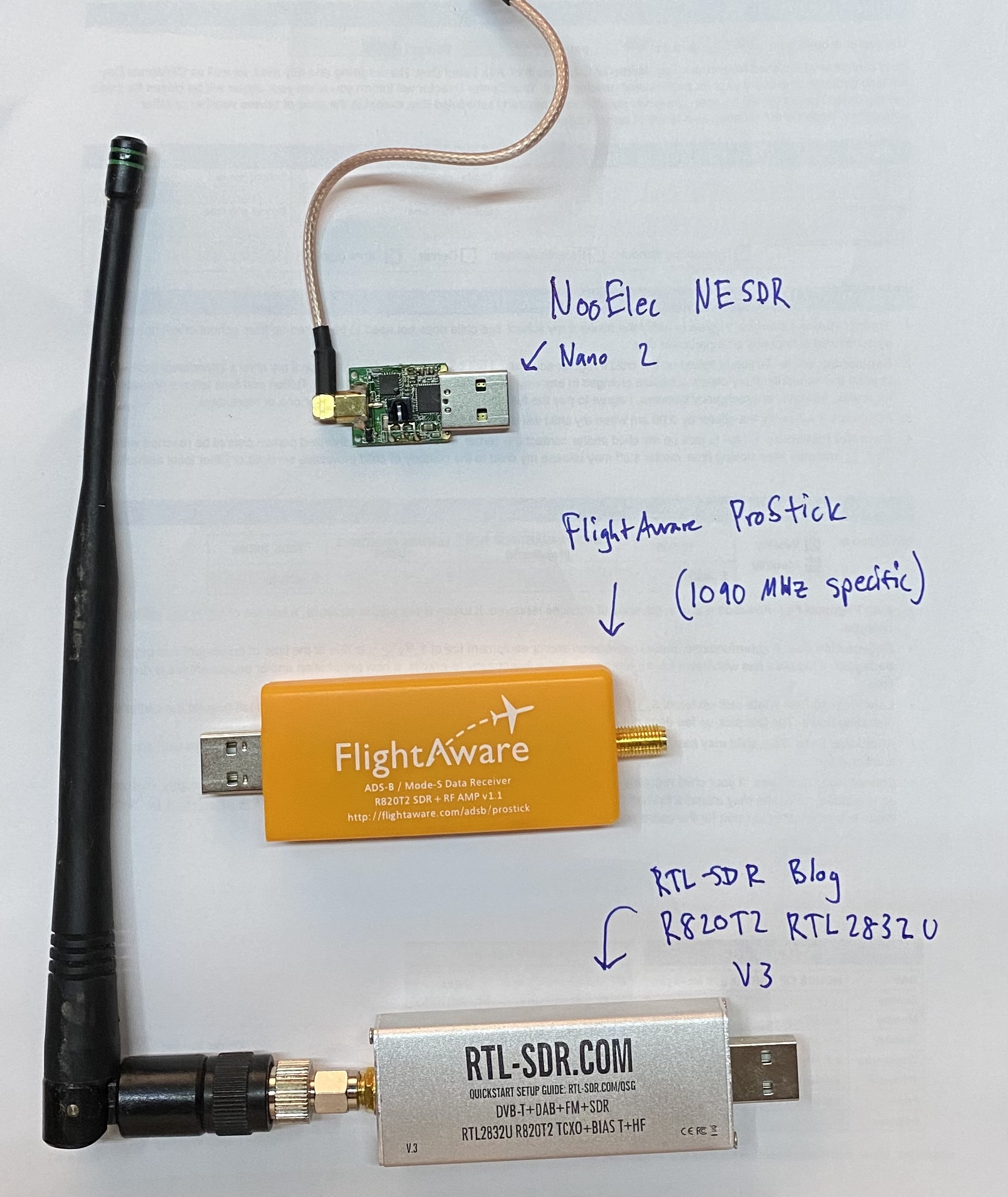
- USB u-blox GPS (VK-172 or GT-U7), GT-U7 preferred because it has a micro-USB plug to connect to your computer. It is important to note that both of these are u-blox modules, which has a binary data format as well as a high default baudrate (57600). These two properties allow for quick transmission of each GPS message from GPS to computer.
- 15-30 minutes
Steps
1 – Update your host machine and install packages
This tutorial is for Linux. I use Ubuntu so we utilize Aptitude (apt) for package management:
sudo apt update
sudo apt upgrade
sudo rpi-update
sudo apt install gpsd gpsd-clients python-gps chrony
2 – Modify GPSd default startup settings
In /etc/default/gpsd, change the settings to the following:
# Start the gpsd daemon automatically at boot time
START_DAEMON="true"

# Use USB hotplugging to add new USB devices automatically to the daemon
USBAUTO="true"

# Devices gpsd should collect to at boot time.
# this could also be /dev/ttyUSB0, it is ACM0 on raspberry pi
DEVICES="/dev/ttyACM0"

# -n means start listening to GPS data without a specific listener
GPSD_OPTIONS="-n"
Reboot with sudo reboot.
3a – Chrony configuration (if using NTPd, go to 3b)
I took the default configuration, added my 10.98 servers, and more importantly, added a reference clock (refclock). Link to chrony documentation here. Arguments/parameters of this configuration file:
- 10.98.1.198 is my microsecond accurate PPS NTP server
- iburst means send a bunch of synchronization packets upon service start so accurate time can be determined much faster (usually a couple seconds)
- maxpoll (and minpoll, which isn’t used in this config) is how many seconds to wait between polls, defined by 2^x where x is the number in the config. maxpoll 6 means don’t wait more than 2^6=64 seconds between polls
- refclock is reference clock, and is the USB GPS source we are adding
- ‘SHM 0’ means shared memory reference 0, which means it is checking with GPSd using shared memory to see what time the GPS is reporting
- ‘refid NMEA’ means name this reference ‘NMEA’
- ‘offset 0.000’ means don’t offset this clock source at all. We will change this later
- ‘precision 1e-3’ means this reference is only accurate to 1e-3 (0.001) seconds, or 1 millisecond
- ‘poll 3’ means poll this reference every 2^3 = 8 seconds
- ‘noselect’ means don’t actually use this clock as a source. We will be measuring the delta to other known times to set the offset and make the source selectable.
pi@raspberrypi:~ $ sudo cat /etc/chrony/chrony.conf
# Welcome to the chrony configuration file. See chrony.conf(5) for more
# information about usuable directives.
#pool 2.debian.pool.ntp.org iburst
server 10.98.1.1 iburst maxpoll 6
server 10.98.1.198 iburst maxpoll 6
server 10.98.1.15 iburst

refclock SHM 0 refid NMEA offset 0.000 precision 1e-3 poll 3 noselect
Restart chrony with sudo systemctl restart chrony.
3b – NTP config
Similar to the chrony config, we need to add a reference clock (called a driver in NTP). For NTP, drivers are “servers” that start with an address of 127.127. The next two octets tell what kind of driver it is. The .28 driver is the shared memory driver, same theory as for chrony. For a full list of drivers, see the official NTP docs. To break down the server:
- ‘server 127.127.28.0’ means use the .28 (SHM) driver
- minpoll 4 maxpoll 4 means poll every 2^4=16 seconds
- noselect means don’t use this for time. Similar to chrony, we will be measuring the offset to determine this value.
- ‘fudge 127.127.28.0’ means we are going to change some properties of the listed driver
- ‘time1 0.000’is the time offset calibration factor, in seconds
- ‘stratum 2’ means list this source as a stratum 2 source (has to do with how close the source is to “true” time), listing it as 2 means other, higher stratum sources will be selected before this one will (assuming equal time quality)
- ‘refid GPS’ means rename this source as ‘GPS’
server 127.127.28.0 minpoll 4 maxpoll 4 noselect
fudge 127.127.28.0 time1 0.000 stratum 2 refid GPS
Restart NTPd with sudo systemctl restart ntp.
4 – check time offset via gpsmon
Running gpsmon shows us general information about the GPS, including time offset. The output looks like the below screenshot. Of importance is the satellite count (on right, more is better, >5 is good enough for time), HDOP (horizontal dilution of precision) is a measure of how well the satellites can determine your position (lower is better, <2 works for basically all navigation purposes), and TOFF (time offset).
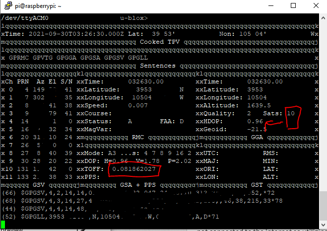
In this screenshot the TOFF is 0.081862027, which is 81.8 milliseconds off the host computer’s time. Watch this for a bit – it should hover pretty close to a certain value +/- 10ms. In my case, I’ve noticed that if there are 10 or less satellites locked on, it is around 77ms. If there are 11 or more, it is around 91ms (presumably due to more satellite information that needs to be transmitted).
5 – record statistics for a data-driven offset
If you are looking for a better offset value to put in the configuration file, we can turn on logging from either chrony or NTPd to record source information.
For chrony:
Edit /etc/chrony/chrony.conf and uncomment the line for which kinds of logging to turn on:
# Uncomment the following line to turn logging on.
log tracking measurements statistics
Then restart chrony (sudo systemctl restart chrony) and logs will start writing to /var/log/chrony (this location is defined a couple lines below the log line in chrony.conf):
pi@raspberrypi:~ $ ls /var/log/chrony
measurements.log  statistics.log  tracking.log
For NTPd (be sure to restart it after making any configuration changes):
austin@prox-3070 ~ % cat /etc/ntp.conf
# Enable this if you want statistics to be logged.
statsdir /var/log/ntpstats/

statistics loopstats peerstats clockstats
filegen loopstats file loopstats type day enable
filegen peerstats file peerstats type day enable
filegen clockstats file clockstats type day enable
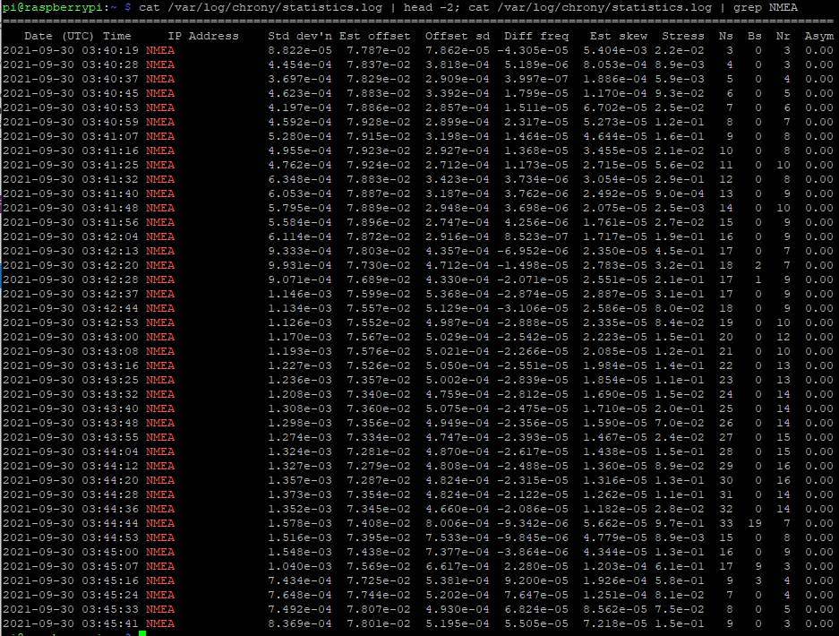
Wait a few minutes for some data to record (chrony synchronizes pretty quick compared to NTPd) and check the statistics file, filtered to our NMEA refid:
cat /var/log/chrony/statistics.log | grep NMEA
This spits out the lines that have NMEA present (the ones of interest for our USB GPS). To include the headers to show what each column is we can run
# chrony
cat /var/log/chrony/statistics.log | head -2; cat /var/log/chrony/statistics.log | grep NMEA

# ntp, there is no header info so we can omit that part of the command
cat /var/log/peerstats | grep 127.127.28.0
NTP stats don’t include header information. The column of interest is the one after the 9014 column. The columns are day, seconds past midnight, source, something, estimated offset, something, something, something. We can see the offset for this VK-172 USB GPS is somewhere around 76-77 milliseconds (0.076-0.077 seconds), which we can put in place of the 0.000 for the .28 driver for NTP and remove noselect.
austin@prox-3070 ~ % cat /var/log/ntpstats/peerstats | grep 127.127.28.0
59487 49648.536 127.127.28.0 9014 -0.078425007 0.000000000 7.938064614 0.000000060
59487 49664.536 127.127.28.0 9014 -0.079488544 0.000000000 3.938033388 0.001063537
59487 49680.536 127.127.28.0 9014 -0.079514781 0.000000000 1.938035682 0.000770810
59487 49696.536 127.127.28.0 9014 -0.079772284 0.000000000 0.938092429 0.000808697
59487 49712.536 127.127.28.0 9014 -0.079711708 0.000000000 0.438080791 0.000661032
59487 49728.536 127.127.28.0 9014 -0.075098563 0.000000000 0.188028843 0.004311958
So now we have some data showing the statistics of our NMEA USB GPS NTP source. We can copy and paste this into Excel, run data to columns, and graph the result and/or get the average to set the offset.
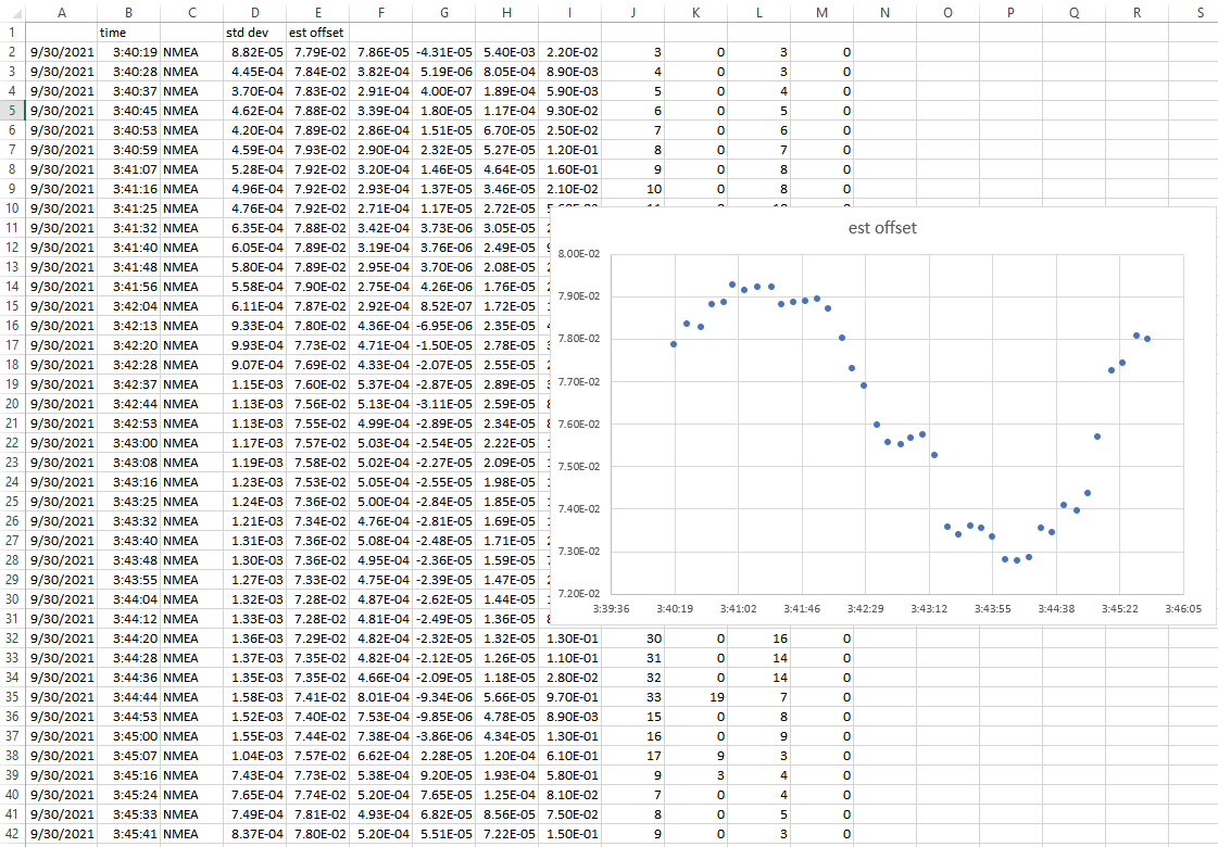
This graph is certainly suspicious (sine wave pattern and such) and if I wasn’t writing this blog post, I’d let data collect overnight to determine an offset. Since time is always of the essence, I will just take the average of the ‘est offset’ column (E), which is 7.64E-2, or 0.0763 seconds. Let’s pop this into the chrony.conf file and remove noselect:
refclock SHM 0 refid NMEA offset 0.0763 precision 1e-3 poll 3
For NTP:
Restart chrony again for the config file changes to take effect – sudo systemctl restart chrony.
6 – watch ‘chrony sources’ or ‘ntpq -pn’ to see if the USB GPS gets selected as the main time source
If you aren’t aware, Ubuntu/Debian/most Linux includes a utility to rerun a command every x seconds called watch. We can use this to watch chrony to see how it is interpreting each time source every 1 second:
# for chrony
watch -n 1 chronyc sources
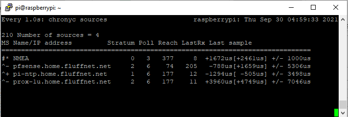
In the above screenshot, we can see that chrony actually has the NMEA source selected as the primary source (denoted with the *). It has the Raspberry Pi PPS NTP GPS ready to takeover as the new primary (denoted with the +). All of the sources match quite closely (from +4749us to – 505us is around 5.2 milliseconds). The source “offset” is in the square brackets ([ and ]).
# for ntp
watch -n 1 ntpq -pn

7- is +/- five millseconds good enough?
For 99% of use cases, yes. You can stop here and your home network will be plenty accurate. If you want additional accuracy, you are in luck. This GPS module also outputs a PPS (pulse per second) signal! We can use this to get within 0.05 millseconds (0.00005 seconds) from official/atomic clock time.
Conclusion
In this post, we got a u-blox USB GPS set up and added it as a reference clock (refclock) to chrony and demonstrated it is clearly within 10 millisecond of official GPS time.
You could write a script to do all this for you! I should probably try this myself…
In the next post, we can add PPS signals from the GPS module to increase our time accuracy by 1000x (into the microsecond range).
A note on why having faster message transmission is better for timing
My current PPS NTP server uses chrony with NMEA messages transmitted over serial and the PPS signal fed into a GPIO pin. GPSd as a rule does minimum configuration of GPS devices. It typically defaults to 9600 baud for serial devices. A typical GPS message looks like this:
$GPGGA, 161229.487, 3723.2475, N, 12158.3416, W, 1, 07, 1.0, 9.0, M, , , , 0000*18
That message is 83 bytes long. At 9600 baud (9600 bits per second), that message takes 69.1 milliseconds to transmit. Each character/byte takes 0.833 milliseconds to transmit. That means that as the message length varies, the jitter will increase. GPS messages do vary in length, sometimes significantly, depending on what is being sent (i.e. the satellite information, $GPGSV sentences, is only transmitted every 5-10 seconds).
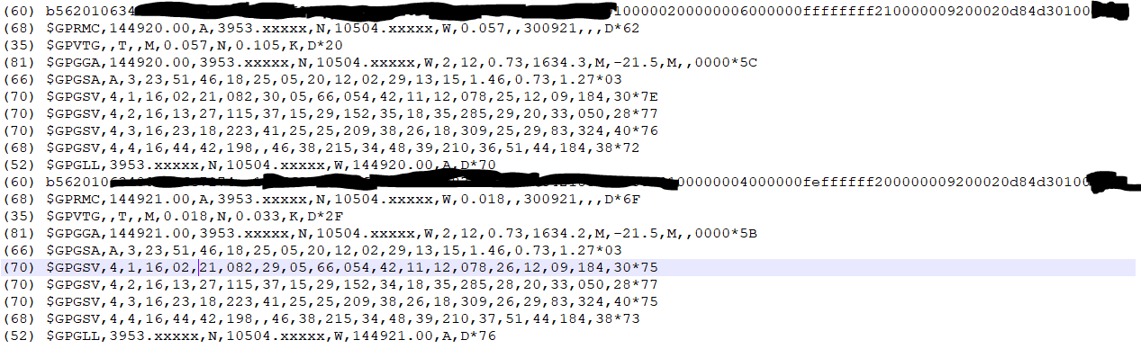
I opened gpsmon to get a sample of sentences – I did not notice this until now but it shows how many bytes each sentence is at the front of the sentence:
(35) $GPZDA,144410.000,30,09,2021,,*59
------------------- PPS offset: -0.000001297 ------
(83) $GPGGA,144411.000,3953.xxxx,N,10504.xxxx,W,2,6,1.19,1637.8,M,-20.9,M,0000,0000*5A
(54) $GPGSA,A,3,26,25,29,18,05,02,,,,,,,1.46,1.19,0.84*02
(71) $GPRMC,144411.000,A,3953.xxxx,N,10504.xxxx,W,2.80,39.98,300921,,,D*44
(35) $GPZDA,144411.000,30,09,2021,,*58
------------------- PPS offset: -0.000000883 ------
(83) $GPGGA,144412.000,3953.xxxx,N,10504.xxxx,W,2,7,1.11,1637.7,M,-20.9,M,0000,0000*52
(56) $GPGSA,A,3,20,26,25,29,18,05,02,,,,,,1.39,1.11,0.84*00
(70) $GPGSV,3,1,12,29,81,325,27,05,68,056,21,20,35,050,17,18,34,283,24*76
(66) $GPGSV,3,2,12,25,27,210,14,15,27,153,,13,25,117,,02,23,080,19*78
(59) $GPGSV,3,3,12,26,17,311,22,23,16,222,,12,11,184,,47,,,*42
------------------- PPS offset: -0.000000833 ------
(71) $GPRMC,144412.000,A,3953.xxxx,N,10504.xxxx,W,2.57,38.19,300921,,,D*48
(35) $GPZDA,144412.000,30,09,2021,,*5B
(83) $GPGGA,144413.000,3953.xxxx,N,10504.xxxx,W,2,7,1.11,1637.6,M,-20.9,M,0000,0000*52
(56) $GPGSA,A,3,20,26,25,29,18,05,02,,,,,,1.39,1.11,0.84*00
(71) $GPRMC,144413.000,A,3953.xxxx,N,10504.xxxx,W,2.60,36.39,300921,,,D*41
(35) $GPZDA,144413.000,30,09,2021,,*5A
These sentences range from 83 bytes to 35 bytes, a variation of (83 bytes -35 bytes)*0.833 milliseconds per byte = 39.984 milliseconds.
Compare to the u-blox binary UBX messages which seem to always be 60 bytes and transmitted at 57600 baud, which is 8.33 milliseconds to transmit the entire message.
The variance (jitter) is thus much lower and can be much more accurate as a NTP source. GPSd has no problem leaving u-blox modules at 57600 baud. This is why the USB GPS modules perform much more accurate for timekeeping than NMEA-based devices when using GPSd.
For basically every GPS module/chipset, it is possible to send it commands to enable/disable sentences (as well as increase the serial baud rate). In an ideal world for timekeeping, GPSd would disable every sentence except for time ($GPZDA), and bump up the baud rate to the highest supported level (115200, 230400, etc.). Unfortunately for us, GPSd’s default behavior is to just work with every GPS, which essentially means no configuring the GPS device.
Update 2024-01-19: RIP Dave Mills, inventor/creator of NTP – https://arstechnica.com/gadgets/2024/01/inventor-of-ntp-protocol-that-keeps-time-on-billions-of-devices-dies-at-age-8