HTTP code 302 redirect loops can be caused by a number of things. Most of them tend to be caused by a misconfigured forward or reverse proxy (Apache, NGINX, HAProxy, etc.). In my case, I am in the process of migrating my austinsnerdythings.com WordPress blog from a single tier (NGINX) stack to a 3-tier application stack. This 3-tier stack consists of HAProxy in the front, Varnish in the middle, and NGINX in the back. A simple header setting missing from my NGINX config caused me to spend about an hour figuring out what was causing my HTTP 302 redirect loop.
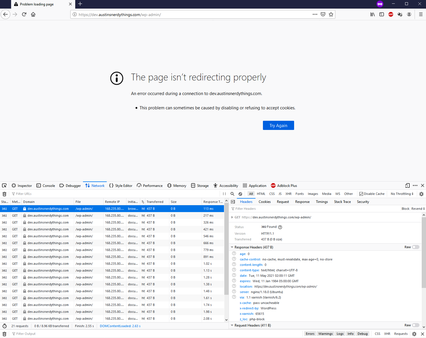
Upon the first visit to my dev site immediately after enabling SSL in the HAProxy config, I was presented with a Firefox error stating “The page isn’t redirecting properly – An error occurred during a connection to dev.austinsnerdythings.com. *this problem can sometimes be caused by disabling or refusing to accept cookies.”. A screenshot of the error (and associated network requests) is presented below. Firefox apparently retried the request 20 times after the initial redirect.
screenshot of HTTP 302 code with associated redirect loop
What’s really going on here
The 3 tiers I’ve selected for my stack each play a distinct role in serving you this webpage. The 3 tiers are:
HAProxy – HAProxy is the first application to see any request to austinsnerdythings.com. It handles SSL (the s in https) and that’s about it. In the future, I can use it to make my site highly available (the HA in HAProxy) and fully redundant but that’s a definitely overkill for now. After dealing with the SSL, it hands off the regular http request to Varnish. HAProxy is fast.
Varnish – is a caching application. That’s all it does. It doesn’t do SSL, which is why we need to stick HAProxy in front. If a page or asset (.js, .css, etc.) hasn’t been accessed recently, Varnish sends the http request to the webserver and stores the result and forwards it back to the original requester (via HAProxy). If a page or asset has been accessed recently, it is stored in memory and is flipped back to HAProxy without even touching the webserver. Varnish is fast.
NGINX – is a event-driven webserver. It takes the http request and fulfills it according to the configuration. For any .php file (basically anything in WordPress), this means sending it to PHP-FPM so the Wordprss code can be executed and a result produced to hand back to NGINX and sent up the tiers.
The request is technically http (not SSL) from exiting HAProxy, through Varnish, and into NGINX. WordPress has at least two features that attempt to send http requests to the equivalent https request. WordPress became unhappy that it was receiving a http request from Varnish (via NGINX) and it turned around and said “don’t use http://dev.austinsnerdythings.com, use https://dev.austinsnerdythings.com”! Varnish and NGINX don’t want https requests. The competing requests turned into the redirect loop.
How to fix the HTTP 302 redirect loop
The solution is pretty easy: you just need to add a single line to your NGINX site config file inside the php block:
fastcgi_param HTTPS 1;
This forces the headers to show the request is in fact a HTTPS request. WordPress is perfectly happy with that and doesn’t try any funny business returning 302 codes.
My full NGINX php block (with credit to where I got this from, nyxi.eu) looks like this:
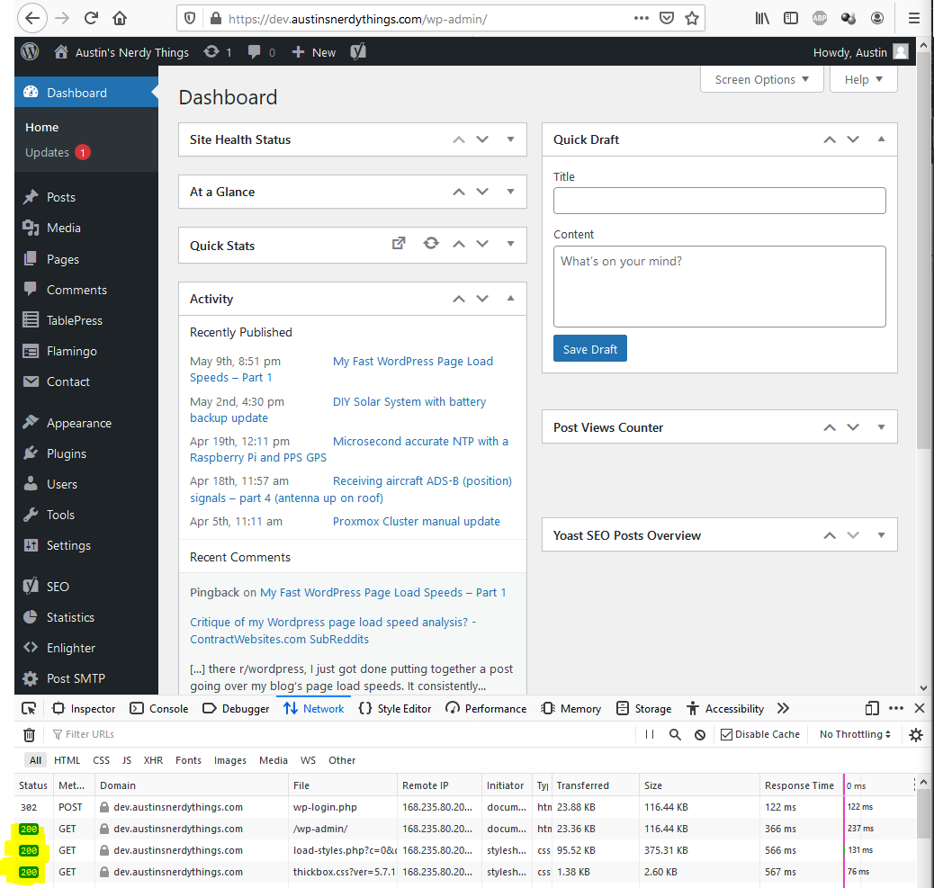
After making the changes and reloading NGINX, I attempted to log in again and was presented with a normal dashboard view with happy, green HTTP 200 codes!
expected screen after attempting to log in after solving the 302 redirect loop
References
Huge shout out to Emil Flink and his post WordPress Nginx redirect loop which really got me pointed in the right direction. He broke down exactly what was happening throughout WordPress’ underlying code and presented it in a a very easy to interpret method.
People trust faster loading web sites than slower ones, all else being equal. There are many articles and studies saying so. It’s also better for search engine optimization (SEO). Personally, if a site takes more than 5 seconds to load, I wonder why and open the page source and start looking into it. I knew when I made austinsnerdythings.com that I wanted it to have a super fast WordPress page load speed.
Initial goal – less than 1 second for page load speed, and >90 for page speed tests
I decided on a initial target of loading in under a second. How did I achieve this target? It wasn’t scientific. Sites that load in 2 seconds or more are noticeable. For sites that load in under a second – it is hard to tell if the site loads in 0.6 seconds or 0.8. One second just felt like a good goal. I also wanted the 3 major page speed test sites to show a 90% or better.
Results – consistently fast WordPress page load speeds and 90+ on page speed tests
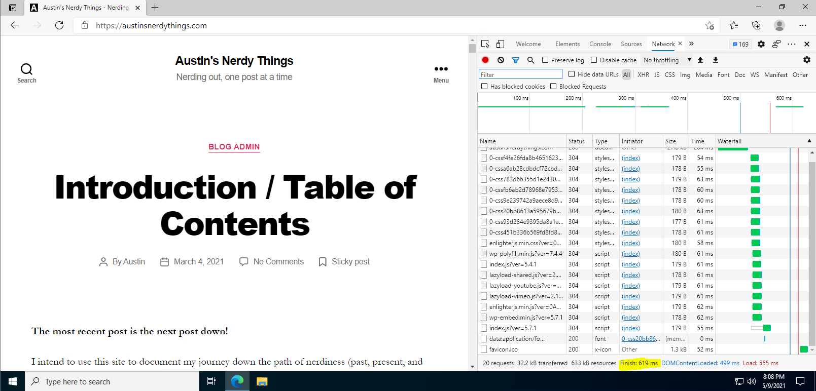
This site consistently loads in under a second. Here is a screenshot from the evening of writing this post showing a load time of 0.619 seconds. The server is located in New York City and I’m loading the page in Denver. That’s 50 milliseconds of ping by itself.
619 millisecond load time on my main PC
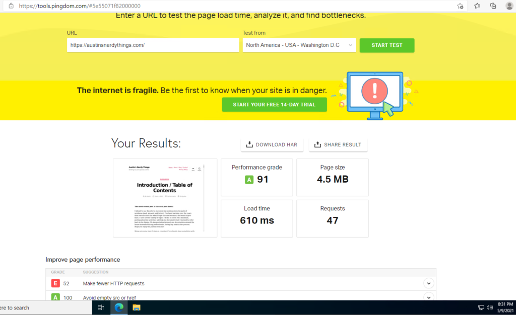
I also score 90+ on each of the big 3 page speed test sites – Google Page Speed Insights, GTMatrix, and Pingdom.
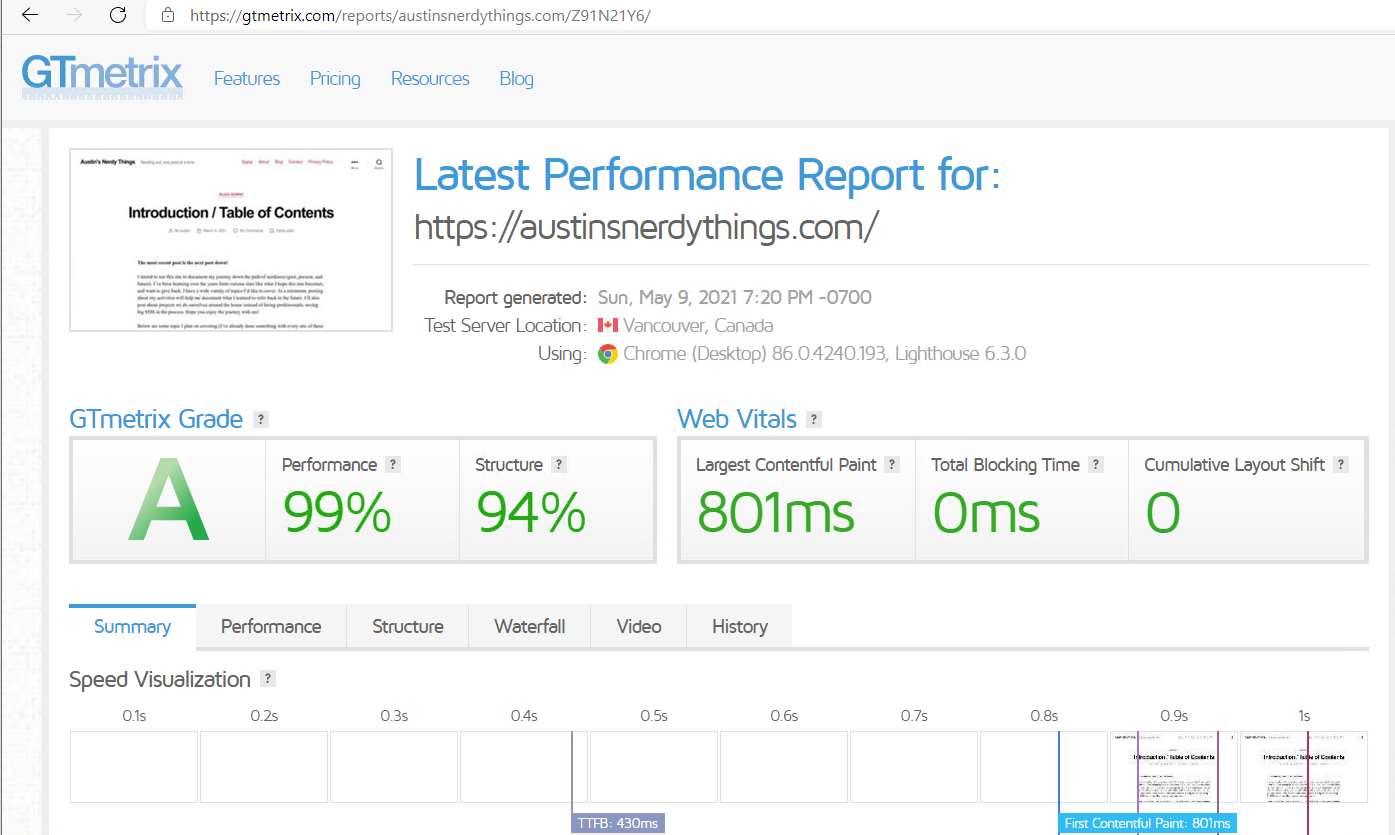
Here is the GTMatrix page speed result showing a strong 99% for performance. Note that this test was conducted from Vancouver, which is nearly 3000 miles away. That’s a lot of distance for the packets to travel.
99% for performance. Can’t argue with that
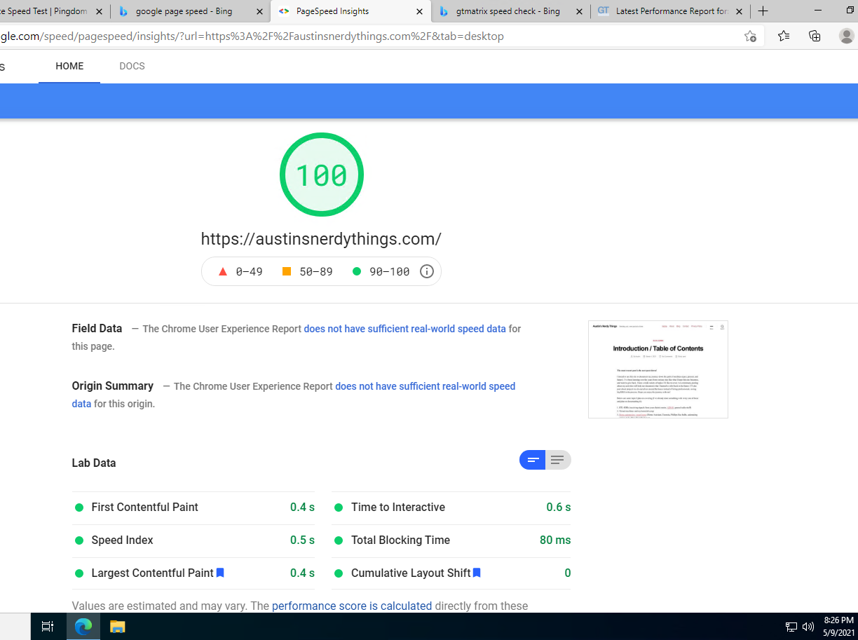
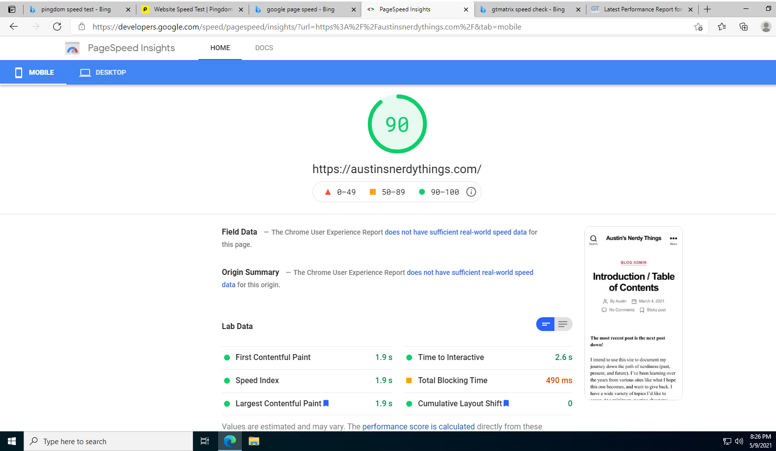
For Google Page Speed Insight, I score a perfect 100 for desktop load speed. Mobile is 90, not sure why they’re so different. I don’t think I need to worry about this anytime soon.
The elusive 100 for Google PageSpeed InsightsPageSpeed reporting 90 for mobile version? Must be some sort of artificial limit on performance or something.
For Pingdom, it is reporting I need to make less HTTP calls. I experimented with a couple different plugins and I think I need to go back to a different one for merging the site’s assets to reduce calls.
I’ve never seen E for a grade. Guessing it basically means F. I should improve on this.
It wasn’t particularly difficult to achieve the 90+ page speed scores and fast WordPress page load speeds. Read on to find out how I did this.
Austinsnerdythings.com stack
The stack driving this site is pretty standard. I use the following (ascending layer order)
Ramnode premium VPS ($12/month). I had a standard VPS but realized a faster CPU would provide better time to first byte and be just faster in general. It also has NVMe drives instead of SATA SSD, which further reduces latency.
Dual stack networking – IPv6 enabled as well as IPv4
MariaDB (MySQL drop in replacement) – zero tuning
PHP-FPM – interprets all dynamic requests, which is basically all the requests. zero tuning
NGINX webserver – this is the new hotness for webservers. It is event driven and runs fast. zero tuning
GZIP compression – much of the content can be compressed while being transferred which means faster load times
HTTP/2 – the newest generation of HTTP transfer protocol. not sure what’s faster about it than HTTP/1.1 but it is
Fast velocity minify plugin – combines javascript and CSS files into fewer entities which means faster load time
No extra plugins – don’t load up on plugins. some are really bad and will drastically increase page load times.
Lazy load pictures – no need to have pictures load until users get to them
Don’t embed videos – they just take forever to load up, which is a problem for page load speeds
Overall, this is a pretty standard stack. I haven’t done any manual tuning to any of the services/processes serving up my site. Starting with a fast VPS definitely helps get a fast WordPress page load speed. The rest just seemed logical to me. That doesn’t mean there isn’t room for improvement.
What’s next for an even faster WordPress page load speed
I have a development environment mocked up on my Proxmox virtual machine host that mimics almost exactly the production site (i.e. what served you this page). The page load speeds were roughly the same locally vs from NYC so it is a good comparison. I installed Varnish for caching and HAProxy for SSL termination (Varnish doesn’t do SSL/https). My homepage loaded consistently in a quarter of a second. The fastest I saw was 0.219 seconds. Sure Varnish and HAProxy are two more full-blown services to install and manage but is it worth it? I think it is. I’ll be migrating my production stack over to this 3 tier stack soon.
Further, I can add my content to a content delivery network (CDN), like Cloudflare, and have it cached there too for fast access anywhere they have a datacenter (they have like 200 datacenters across the planet). I did use Cloudflare CDN for a bit and didn’t like not seeing my statistics update in real-time so I backed off.
I am realizing this may be a good business opportunity – consistently super fast WordPress sites. Let me know if you’d be interested.
Check back for part 2 where I document the journey to the 3 tier stack.
As of 5/1/2021, all of the main components of my DIY solar system with battery backup have arrived. I posted about the requirements, component select, and some fun with shipping from China in my initial solar post – Planning my 600W DIY solar system with 6 kWh battery backup. If you want some background of how we got here, head to that link then come on back.
Background
To recap, my DIY solar system with battery backup consists of a few main components:
8x 260 amp hour prismatic LiFePO4 battery cells. They will be placed in series for a 24V nominal system with around 6.0 kilowatt hours of usable storage.
MPP LV2424 hybrid all-in-one inverter. This device handles converting direct current (DC, like a car battery) to alternating current (AC, like household outlets) and charging the batteries
2x 310W Canadian solar panels. These will be wired in series for 72V maximum power point voltage.
8S JBD 100A battery management system – to protect the batteries from a number of undesirable conditions
The other miscellaneous things that I need are: battery bus bars, wiring, ring terminals, and general connection things.
Materials arriving and resting battery voltages
We were on vacation when the batteries (and inverter) arrived so they sat for a few days before I got a chance to unbox them. The batteries were very well packaged and I can’t thank Battery Hookup enough for how fast they shipped after what I’ve been dealing with from China.
battery cells unpacked
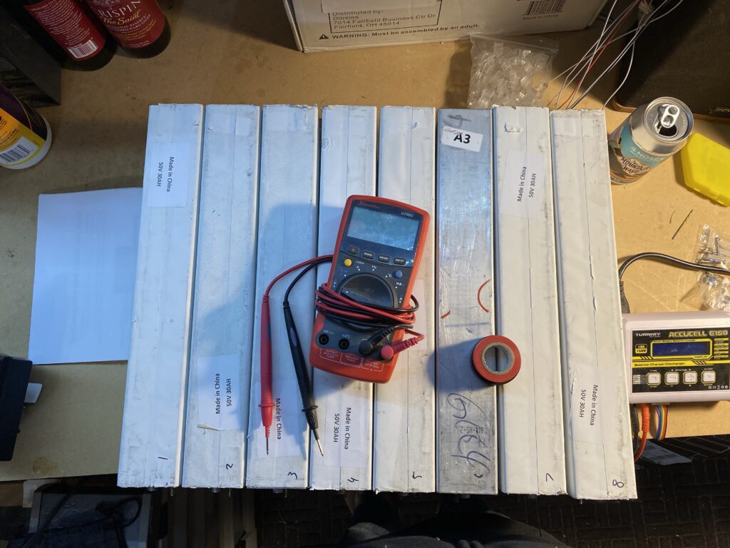
Upon unboxing, I made sure to record the resting voltage of each cell. Below were the resting voltages:
cell
voltage
1
3.341
2
3.345
3
3.435
4
3.339
5
3.351
6
3.376
7
3.343
8
3.363
min
3.339
max
3.435
avg
3.362
delta
0.096
Resting voltages of the 260 amp hour BYD LiFePO4 cells
Cell #2 had the lowest voltage and cell #3 the highest. This presented an easy chance to test out my bus bars for voltage equalization. I did not measure the cell internal resistance so I wasn’t really sure how much current would flow from cell 3 to 2 when shorted together so I did a quick estimate based on Ohm’s law (V=IR -> I=V/R). With an estimated internal resistance (IR) of 20 milliohms (I’ve had LiPo in this range after some degradation), and a voltage difference of 0.096V, that would mean a current of 0.096/0.020=4.8A. That wasn’t a huge number so I was comforable just connecting the cells with the bus bars. But first I wanted to actually measure with a multimeter.
I was expecting about 5A based on the calculation above. I’m not sure how I was 10x off on the estimate but after hooking up my multimeter, the equalization current was 0.6A. That was plenty low so I set my mind to balancing. But before that, I needed bus bars to connect all the cells in parallel.
Constructing copper bus bars
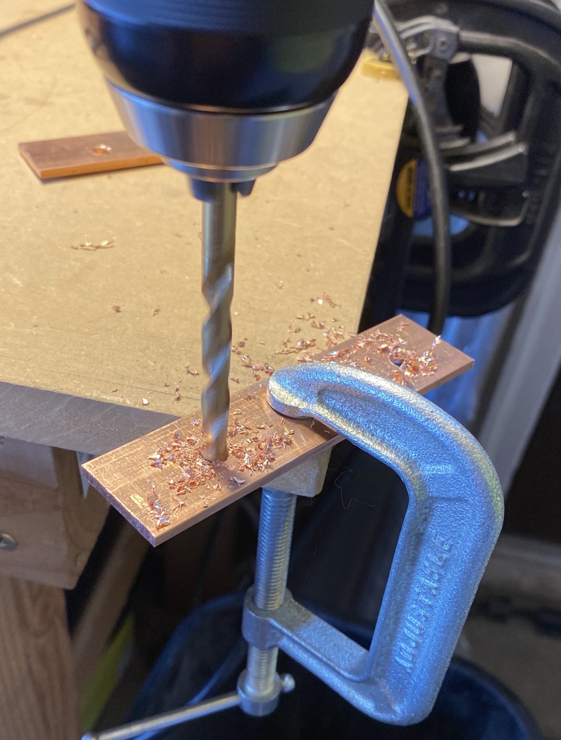
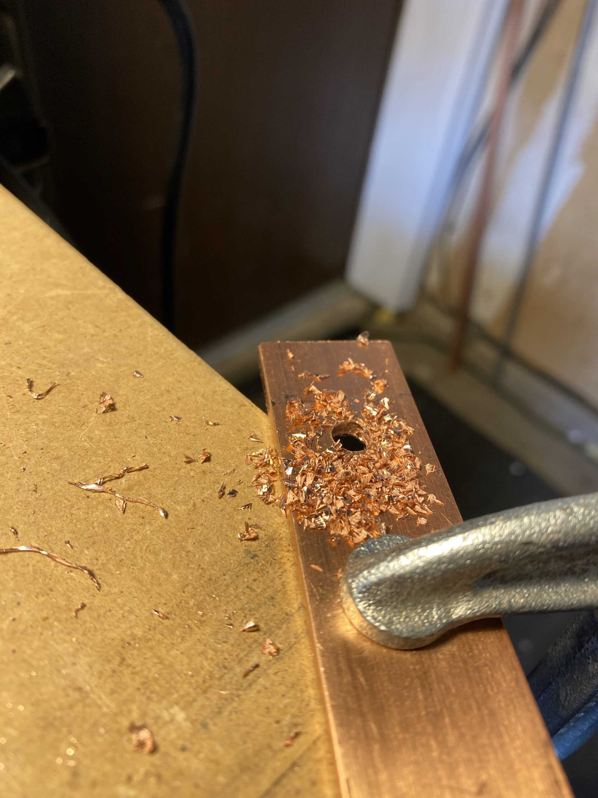
Bus bars are used to conduct high amounts of current in electrical applications. In essence, they are oversized, flat wires. I ordered 2x copper bars from McMaster Carr that are 1″x1/8″x3′. They arrived in two days with free shipping… Amazon is gaining competition. I got to work drilling holes.
copper bus bars ready for drilling with marks spaced 2.5″ apartdrilling 2mm pilot holedrilling 6mm final holecopper shards after drillingfiling down rough edges
Heat shrinking the cells
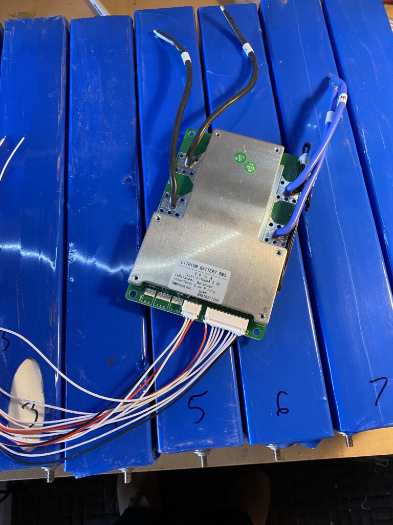
With the bus bars ready, it was time to heat shrink the battery cells. Battery Hookup said they were uncovered and needed to be heat shrunk for every cell. Turns out 7 of 8 had a covering on them already. I heat shrunk them anyways for two reasons: 1) to further protect the cells from damage and short circuits and 2) so they look better. The cell on the left will be re-done with more heat shrink. I guestimated how much I needed and was short a few inches.
cells ready for heat shrinkcells heat shrunk with BMS on top
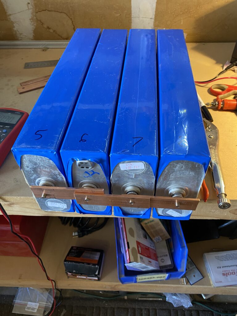
Balancing in 2 sets of 4 cells each
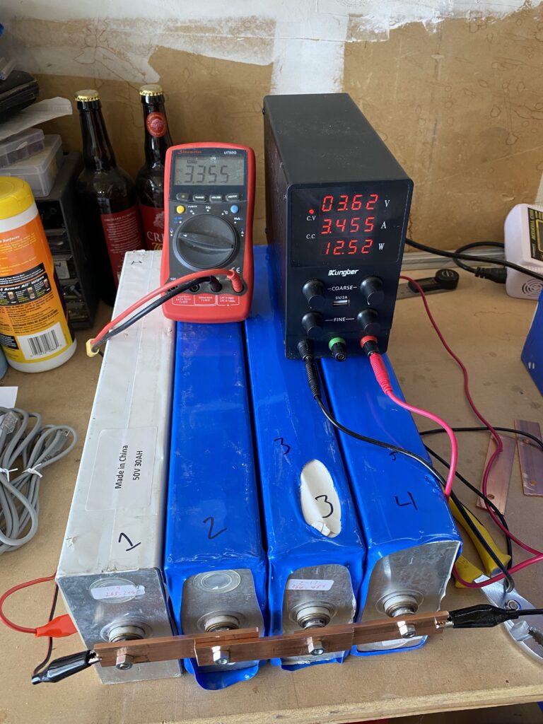
When making the bus bars, I put together a mental picture of what I needed to make and how many I needed. This worked fine for the final battery but I would need double for balancing. I had the full extra 3′ copper bar but it took forever to cut so I just decided to balance the cells in 2 groups of 4. Balancing is charging all cells in parallel as one low voltage, giant capacity battery to their rated voltage (3.65V for LiFePO4). Doing 4 cells at a time meant it was a 3.2V battery with a capacity of 1040 amp hours. The resting voltages were in the upper end of the voltage curve chart so it wouldn’t take super long. If the battery was fully depleted, it would take 104 hours at the 10 amps my bench power supply puts out.
So I got the bus bars hooked up and started balancing by setting my power supply to 3.65V and current to max.
battery cells hooked up in parallel (4x cells in parallel means a single 3.2V 1000Ah “cell”)
Measurement discrepancies and voltage drop
The first thing I did when I started charging was take voltage measurements to make sure things were right. I noticed some irregularities.
The first irregularity was the fact that the bench power supply was over-reporting the voltage by 0.034V or so when comparing the display to the terminals. This isn’t a huge deal and is actually a pretty decent level of accuracy for a $40 bench power supply from Amazon.
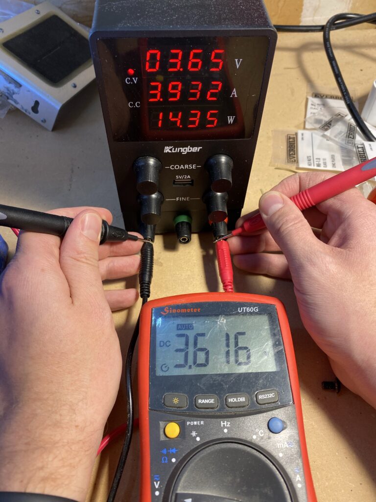
verifying DC power supply output voltage (set to 3.650V, actual output is 3.614V)
The next thing I noticed is that for a 10A power supply, it is putting out a lot less than 10A. So I measured the voltage at the bus bars.
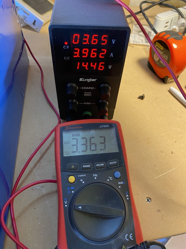
measuring voltage at bus bars. this is a pretty big voltage drop through the charger wires. 3.616V at the terminals – 3.363V at the bus bars is 0.253V drop. At 3.962A, that is a resistance of (V=IR -> V/I=R) 0.063 ohms. the wires were warm.
By leaving the voltage set to 3.65V at the DC power supply, the voltage drop means I wouldn’t get anywhere the rated 10A. The actual drop would decrease proportionally as the battery voltage neared the terminal voltage.
Regardless, it only took a couple hours until the cells were topped off for each set of 4. They are currently resting. I will check their voltages again tomorrow morning. The amount the cells drop in voltage from where they left off indicates the strength of the cell, with larger drops meaning weaker cells.
the very start of balancing the 2nd set of 4 cells. I do intend to rewrap cell 3 and wrap cell 1 when my next batch of shrinkwrap arrives.
Conclusion
This is where we will leave off for the day. The 8 cells have been balanced in 2 groups of 4 and are currently resting. After 24 hours I will recheck the voltages to see which cells are strong and which are weak. I need to buy more electrical tape to cover up the bus bar ends (I did start assembling the full battery but stopped because the potential for short-circuit was higher than I was comfortable with).
Lots of acronyms in that title. If I expand them out, it says – “microsecond accurate network time protocol with a Raspberry Pi and pulse per second global positioning system [receiver]”. What it means is you can get super accurate timekeeping (1 microsecond = 0.000001 seconds) with a Raspberry Pi and a GPS receiver (the GT-U7 is less than $12) that spits out pulses every second. By following this guide, you will your very own Stratum 1 NTP server at home!
2025 Update – I wrote a new post with some newer best practices and guidance for 2025, including how to synchronize machines with nanosecond precision using PTP (precision time protocol). Read that post first then come back here – not all discussion is in both places.
Why would you need time this accurate at home?
You don’t. There aren’t many applications for this level of timekeeping in general, and even fewer at home. But this blog is called Austin’s Nerdy Things so here we are. Using standard, default internet NTP these days will get your computers to within a 10-20 milliseconds of actual time (1 millisecond = 0.001 seconds). By default, Windows computers get time from time.windows.com. MacOS computers get time from time.apple.com. Linux devices get time from [entity].pool.ntp.org, like debian.pool.ntp.org. PPS gets you to the next SI prefix in terms of accuracy (milli -> micro), which means 1000x more accurate timekeeping.
You should update your Pi to latest before basically any project. We will install some other packages as well. pps-tools help us check that the Pi is receiving PPS signals from the GPS module. We also need GPSd for the GPS decoding of both time and position. I use chrony instead of NTPd because it seems to sync faster than NTPd in most instances and also handles PPS without compiling from source (the default Raspbian NTP doesn’t do PPS) Installing chrony will remove ntpd.
In /boot/config.txt, add ‘dtoverlay=pps-gpio,gpiopin=18’ to a new line. This is necessary for PPS. If you want to get the NMEA data from the serial line, you must also enable UART and set the initial baud rate.
sudo bash -c "echo '# the next 3 lines are for GPS PPS signals' >> /boot/config.txt"
sudo bash -c "echo 'dtoverlay=pps-gpio,gpiopin=18' >> /boot/config.txt"
sudo bash -c "echo 'enable_uart=1' >> /boot/config.txt"
sudo bash -c "echo 'init_uart_baud=9600' >> /boot/config.txt"
In /etc/modules, add ‘pps-gpio’ to a new line.
sudo bash -c "echo 'pps-gpio' >> /etc/modules"
Reboot
sudo reboot
2 – wire up the GPS module to the Pi
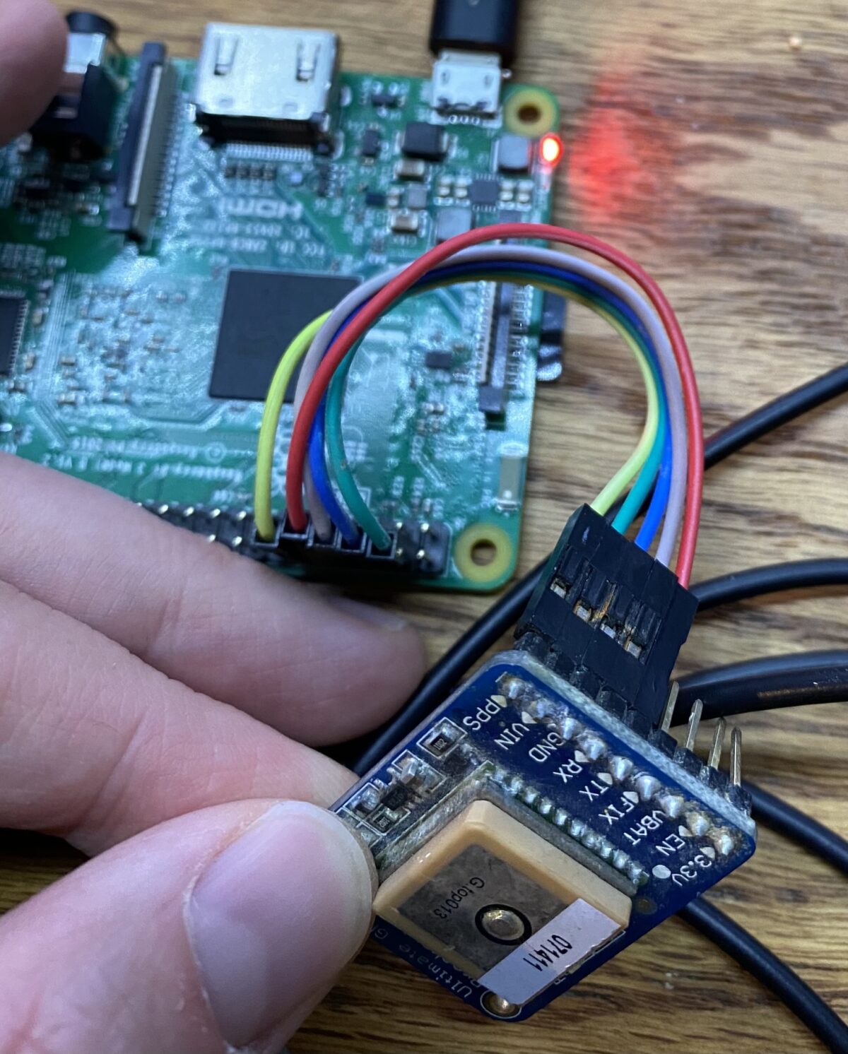
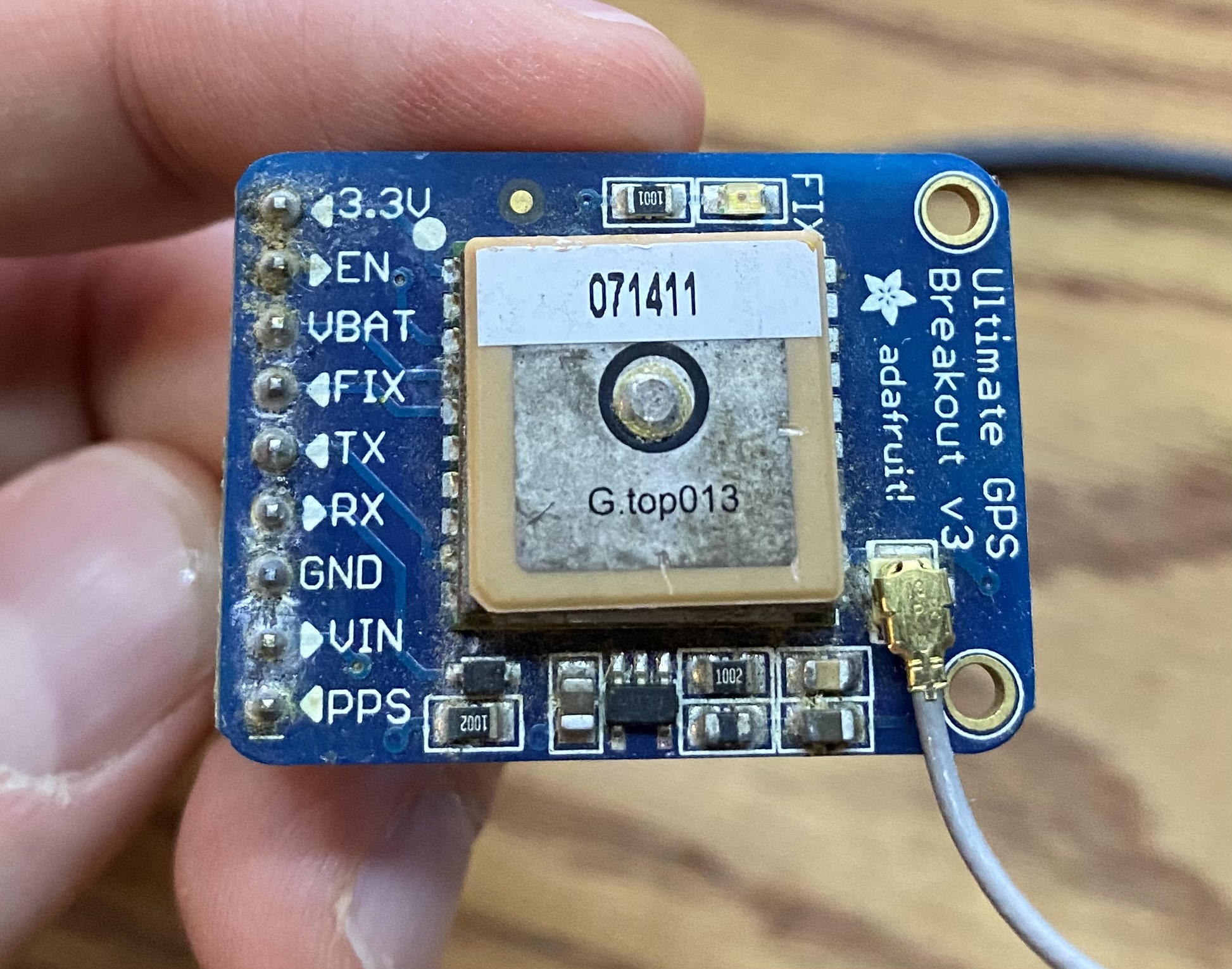
I used the Adafruit Ultimate GPS breakout. It has 9 pins but we are only interested in 5. There is also the Adafruit GPS hat which fits right on the Pi but that seems expensive for what it does (but it is significantly neater in terms of wiring).
Pin connections:
GPS PPS to RPi pin 12 (GPIO 18)
GPS VIN to RPi pin 2 or 4
GPS GND to RPi pin 6
GPS RX to RPi pin 8
GPS TX to RPi pin 10
see 2nd picture for a visual
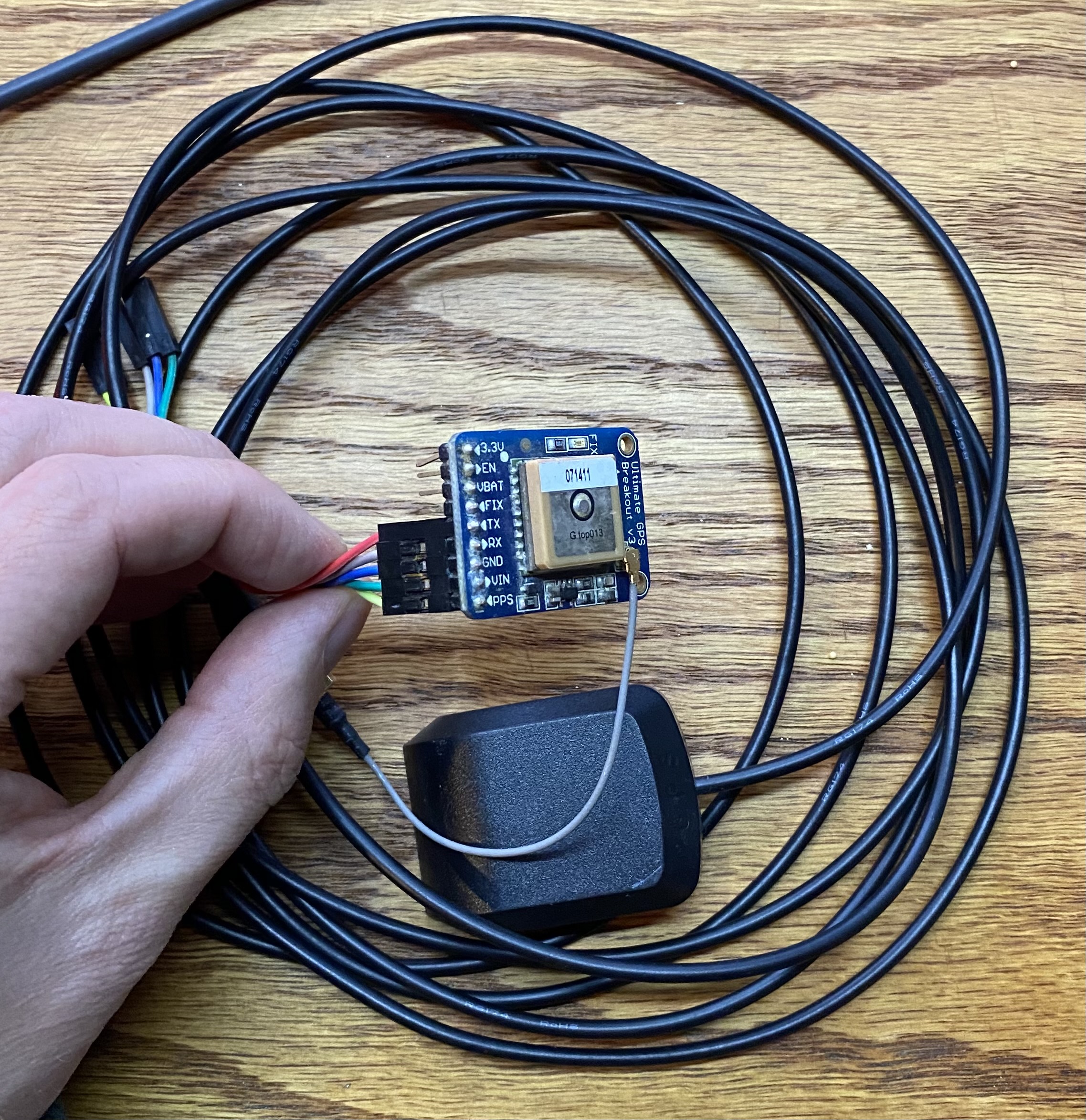
Adafruit Ultimate GPS Breakout V3We use 5 wires total. GPS PPS to pin 12 (GPIO 18), GPS VIN to pin 2 or 4, GPS GND to pin 6, GPS RX to pin 8, GPS TX to pin 10.GPS with wires attached to the board (but not to the Pi) and the antenna. The antenna has a SMA connector, and there is another adapter that is SMA to u.fl to plug into the GPS board.
Now place your GPS antenna (if you have one) in a spot with a good view of the sky. If you don’t have an antenna, you might have to get a bit creative with how you locate your Raspberry Pi with attached GPS.
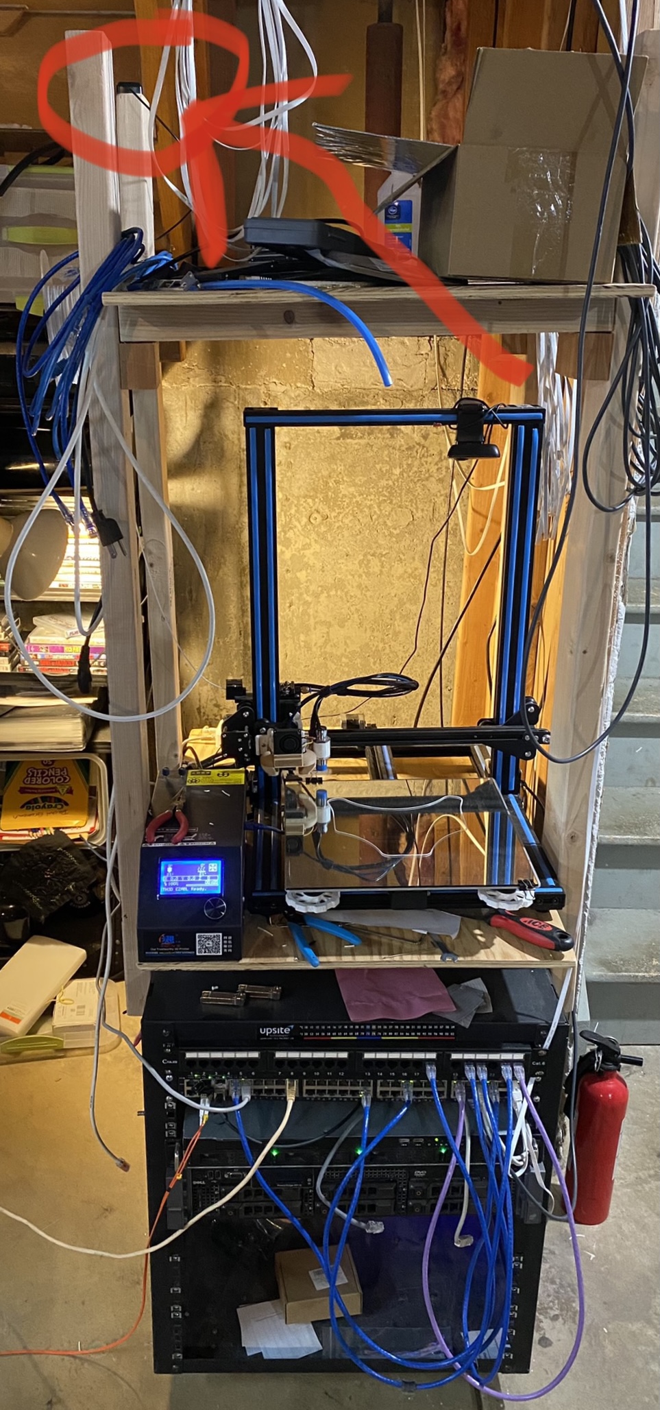
I honestly have my antenna in the basement (with only the kitchen and attic above) and I generally have 8-10 satellites locked all the time (11 as of writing). Guess that means the antenna works better than expected! Either way, better exposure to the sky will in theory work better. Pic:
My super awesome placement of the GPS antenna on top of the wood “cage” (?) I built to hold my 3d printer on top of my server rack. I guess this is a testimony for how well the GPS antenna works? It has 11 satellites locked on as of writing, with a HDOP of 0.88. The components in this rack (Brocade ICX6450-48P, 1U white box with Xeon 2678v3/96GB memory/2x480GB enterprise SSDs/4x4TB HDDs, Dell R710 with 4x4TB and other stuff) will be detailed in an upcoming post.
2.5 – free up the UART serial port for the GPS device
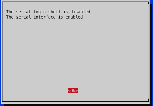
Run raspi-config -> 3 – Interface options -> I6 – Serial Port -> Would you like a login shell to be available over serial -> No. -> Would you like the serial port hardware to be enabled -> Yes.
The output should spit out a new line every second that looks something like this (your output will be a bit farther from x.000000 since it isn’t yet using the GPS PPS):
Edit /etc/default/gpsd and change GPSD_OPTIONS=”” to GPSD_OPTIONS=”-n” and change DEVICES=”” to DEVICES=”/dev/ttyS0 /dev/pps0″, then reboot. My full /etc/default/gpsd is below:
pi@raspberrypi:~ $ sudo cat /etc/default/gpsd
# Default settings for the gpsd init script and the hotplug wrapper.

# Start the gpsd daemon automatically at boot time
START_DAEMON="true"

# Use USB hotplugging to add new USB devices automatically to the daemon
USBAUTO="true"

# Devices gpsd should collect to at boot time.
# They need to be read/writeable, either by user gpsd or the group dialout.
DEVICES="/dev/ttyS0 /dev/pps0"

# Other options you want to pass to gpsd
GPSD_OPTIONS="-n"
sudo reboot
4.5 – check GPS for good measure
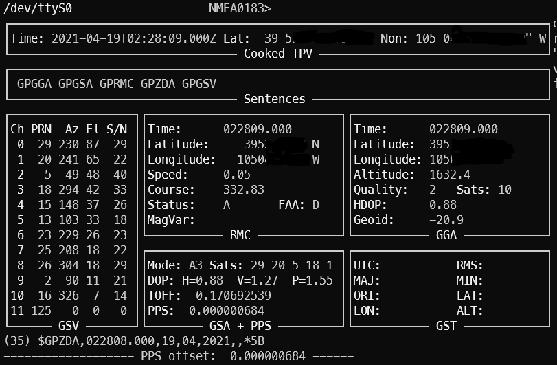
To ensure your GPS has a valid position, you can run gpsmon or cgps to check satellites and such. This check also ensures GPSd is functioning as expected. If your GPS doesn’t have a position solution, you won’t get a good time signal. If GPSd isn’t working, you won’t get any updates on the screen. The top portion will show the analyzed GPS data and the bottom portion will scroll by with the raw GPS sentences from the GPS module.
gpsmon showing 10 satellites used for the position with HDOP of 0.88. This indicates a good position solution which means the time signals should be good as well. The PPS of 0.000000684 indicates the Raspberry Pi is only 684 nanoseconds off of GPS satellite time.
5 – edit config files
For chrony, add these two lines to the /etc/chrony/chrony.conf file somewhere near the rest of the server lines:
2025 update: see the newer post chrony config for how to get single source (i.e. just your single GPS to use both NMEA and PPS) timing to works successfully.
My entire /etc/chrony/chrony.conf file looks like this:
###### below this line are custom config changes #######
server 10.98.1.1 iburst minpoll 3 maxpoll 5
server time-a-b.nist.gov iburst
server time-d-b.nist.gov
server utcnist.colorado.edu
server time.windows.com
server time.apple.com

# delay determined experimentally by setting noselect then monitoring for a few hours
# 0.325 means the NMEA time sentence arrives 325 milliseconds after the PPS pulse
# the delay adjusts it forward
refclock SHM 0 delay 0.325 refid NMEA
refclock PPS /dev/pps0 refid PPS

allow 10.98.1.0/24 # my home network
###### above this line are custom config changes #######

###### below this line is standard chrony stuff #######
keyfile /etc/chrony/chrony.keys
driftfile /var/lib/chrony/chrony.drift
#log tracking measurements statistics
logdir /var/log/chrony
maxupdateskew 100.0
hwclockfile /etc/adjtime
rtcsync
makestep 1 3
Restart chrony, wait a few minutes, and verify.
sudo systemctl restart chrony
5 – verify the NTP server is using the GPS PPS
Right after a chrony restart, the sources will look like this (shown by running ‘chronyc sources’)
For the S column, * means the source that is active. + means it is considered a good source and would be used if the current one is determined to be bad or is unavailable. The x shown for the NMEA source means it is a “false ticker”, which means it isn’t being used. In our case that is fine because the PPS source is active and valid. Anything else generally means it won’t be used.
In this case, chrony is using the PPS signal. The value inside the brackets is how far off chrony is from the source. It is showing that we are 289 nanoseconds off of GPS PPS time. This is very, very close to atomic clock level accuracy. The last column (after the +/-) includes latency to the NTP source as well as how far out of sync chrony thinks it is (for example, the 17.253.2.253 server is 12.5 milliseconds away one-way via ping):
pi@pi-ntp:~ $ ping -c 5 17.253.2.253
PING 17.253.2.253 (17.253.2.253) 56(84) bytes of data.
64 bytes from 17.253.2.253: icmp_seq=1 ttl=54 time=25.2 ms
64 bytes from 17.253.2.253: icmp_seq=2 ttl=54 time=27.7 ms
64 bytes from 17.253.2.253: icmp_seq=3 ttl=54 time=23.8 ms
64 bytes from 17.253.2.253: icmp_seq=4 ttl=54 time=24.4 ms
64 bytes from 17.253.2.253: icmp_seq=5 ttl=54 time=23.4 ms

--- 17.253.2.253 ping statistics ---
5 packets transmitted, 5 received, 0% packet loss, time 4007ms
rtt min/avg/max/mdev = 23.403/24.954/27.780/1.547 ms
A day after the bulk of writing this post, I turned on logging via the .conf file and restarted chrony. It settled to microsecond level accuracy in 57 seconds. For the offset column, the scientific notation e-7 means the results are in nanoseconds. This means that for the 19:54:35 line, the clock is -450.9 nanoseconds off of the PPS signal. There is that e-10 line in there which says that it is 831 picoseconds off PPS (I had to look up SI prefixes to make sure pico came after nano! also I doubt the Pi can actually keep track of time that closely.). After the initial sync, there is only 1 line in the below log that is actually at the microsecond level (the others are all better than microsecond) – the 20:00:59 entry, which shows the clock is -1.183 microseconds off.
Things that affect timekeeping on the Pi
Thought I’d toss in this section for completeness (i.e. thanks for all the good info Austin but how can I make this even better?). There are a few things that affect how well the time is kept on the Pi:
Ambient temperature around the Pi – if you plot the freq PPM against ambient temperature, there will be a clear trend. The more stable the ambient temp, the less variation in timekeeping.
Load on the Pi – similar to above. Highly variable loads will make the processor work harder and easier. Harder working processor means more heat. More heat means more variability. These crystals are physical devices after all.
GPS reception – they actually making timing GPS chips that prefer satellites directly overhead. They have better ability to filter out multipathing and such. In general, the better the GPS reception, the better the PPS signal.
Conclusion
After running through the steps in this guide, you should now have a functional Stratum 1 NTP server running on your Raspberry Pi with microsecond level accuracy provided by a PPS GPS. This system can obtain time in the absence of any external sources other than the GPS (for example, internet time servers), and then sync up with the extremely precise GPS PPS signal. Our NTP GPS PPS clock is now within a few microseconds of actual GPS time.
Coming from part 3, where I wanted to move the antenna, I finally got the antenna up on the roof. Our chimney was decommissioned by the previous owners and as far as I can tell, there isn’t brick under the siding (also why does our chimney have siding on it). So it is sitting a little lower than it should be but it is basically at the highest position of the roof. This has dramatically increased the ability to receive aircraft ADS-B signals.
Results
The results are pretty amazing. We’ve had bad weather for a week now but it’s going to be a clear day today. As of 9:12AM, my Raspberry Pi PiAware ADS-B signal receiver sees 116 aircraft, of which 103 are reporting positions. It is receiving 607 messages per second. The map looks like this:
116 aircraft signals received, 103 with position. farthest out is 190 NM.
You can see aircraft lining up to arrive into KDEN spaced out at regular intervals. It’s also picking up 3 planes on the ground at KBJC which is the closest airport to the antenna.
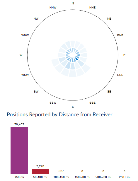
FlightAware has a cool radar type map that shows positions by compass direction and distance. The numbers speak for themselves.
Before
Max distance reported is in the 100-150 nm bucket (327 total reports)
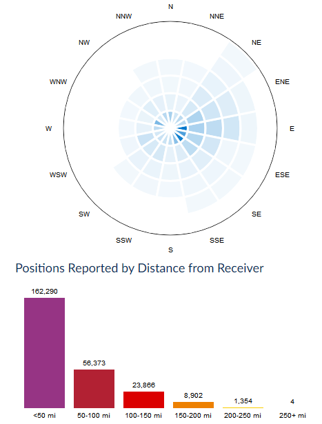
After
That same 100-150 nm bucket now has 24k reports
Interesting features
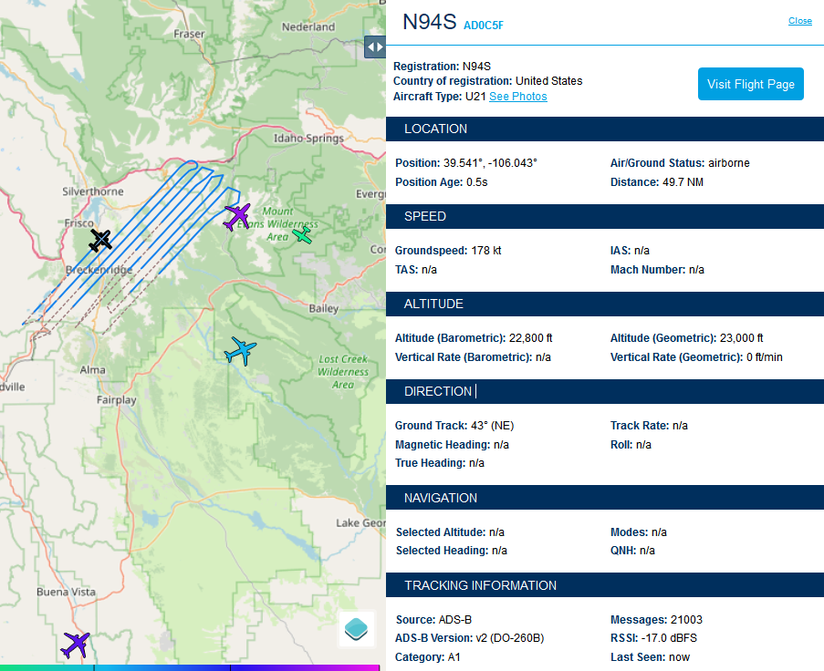
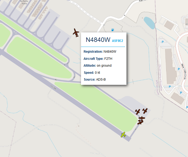
While typing this post, the position count increased to 118. There are some interesting features I’m seeing – a survey plane over the Breckenridge area, a lot of planes on the ground at KBJC (not line of sight to my antenna), and even plane on the ground at KDEN (KDEN is definitely not line of sight to my antenna).
Survey grid being flown by N94S
Planes on the ground at KBJC
I see 4 Cessna/trainer type planes waiting for takeoff for 30R at KBJC. I’m even picking up a corporte jet type aircraft on the ground by the hangars (N4840W). None of this is line of sight to my antenna. There’s a chance the ADS-B signals are bouncing off buildings or something. I shouldn’t be seeing these.
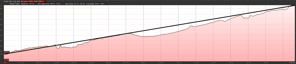
The elevation profile to 30R at KBJC. Antenna on left, run up area on the right. Barely not LOS (line of sight).
Plane on the ground at KDEN
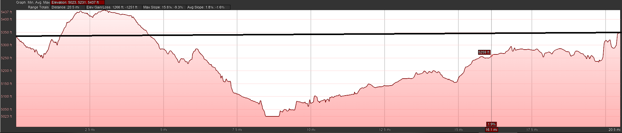
United UAL364 / N802UA (an Airbus A319) on the ground on runway 16L/34R heading southElevation profile to south end of 16L/34R at KDEN. Antenna on left, 16L/34R on right. Definitely not LOS. No idea how I’m picking up these signals. I see a plane on the ground at KDEN multiple times a day since moving the antenna.
151 planes!
I started this post around 9am on 4/18. Just before noon, there were 151 planes being tracked by my PiAware station! 773 messages per second. Notice that plane way out there over west central Nebraska – that’s probably 210 NM out!
Conclusion
Moving my FlightAware ADS-B antenna to the roof drastically increased the range and messages received. As a reminder from when I detailed the equipment in Post 2 – the antenna feeds a 1090MHz ADS-B filter, which in turn feeds the FlightAware Pro Stick. I don’t think I’ll make any other changes to the system other than put it on a battery with solar charger.